Rupture Disc Operating Ratio Explained (Avoid Premature Failure)
Rupture Disc Operating Ratio Explained (Avoid Premature Failure) If your pressure relief devices are blowing during normal plant operations, you are likely suffering from premature metal fatigue. This happens when your process runs too close to the disc’s breaking point. To prevent these expensive, nuisance shutdowns, you must strictly control your rupture disc operating ratio. Understanding this simple metric ensures you select a disc capable of surviving your daily pressure cycles without weakening. Quick Comparison: Allowable Ratios by Disc Design Rupture Disc Type Loading Type Max Operating Ratio Risk of Premature Fatigue Forward-Acting (Standard) Tension 70% to 80% High (if ratio is exceeded) Reverse-Acting (Buckling) Compression 90% to 95% Very Low Graphite Brittle / Shear 80% Moderate What is a Rupture Disc Operating Ratio? The rupture disc operating ratio is the mathematical relationship between your system’s everyday working pressure and the disc’s rated burst pressure. The Definition: It is the maximum percentage of the burst pressure that your system can safely operate at continuously. The Formula: Normal Operating Pressure ÷ Marked Burst Pressure = Operating Ratio. The Goal: To leave a wide enough safety buffer so the metal dome does not stretch, deform, or fatigue during normal daily pressure fluctuations. Why the “90% Rule” Matters for Plant Safety Engineers often refer to the “90% rule” when designing high-efficiency pipelines. Pushing past a disc’s specific ratio limit guarantees failure. Micro-Stretching: When pressure constantly pushes near a disc’s limit, the molecular structure of the metal begins to stretch irreversibly. Drifting Burst Pressures: A fatigued disc will no longer burst at its stamped rating. It will burst much lower, causing unexpected plant shutdowns. Pulsation Damage: If your pipeline features heavy pumps or compressors, the constant pulsing will accelerate metal fatigue even faster if your operating ratio is too tight. How Disc Engineering Alters the Ratio Not all discs can handle high operating ratios. You must match the mechanics to your process. Forward-Acting Limitations These discs face the process and stretch outward (tension loading). Because tension constantly weakens the metal, they are strictly limited to a 70% or 80% operating ratio. Reverse-Acting Advantages The dome faces against the process (compression loading). Metal resists compression incredibly well, allowing these discs to operate safely up to 90% or 95% of their burst pressure without fatiguing. How to Calculate and Apply the Ratio Do not guess your safety margins. Follow these exact steps to specify the right disc for your line: Step 1: Identify Normal Pressure. Determine the absolute highest pressure your system runs at during normal, non-emergency operations (e.g., 75 PSI). Step 2: Identify Burst Pressure. Determine the critical pressure where the disc must burst to save the vessel (e.g., 100 PSI). Step 3: Do the Math. 75 PSI ÷ 100 PSI = 0.75 (or a 75% ratio). Step 4: Make the Selection. Since 75% exceeds the safe limit of a standard forward-acting disc (usually 70%), you must upgrade to a reverse-acting disc to guarantee a long service life. FAQ – Rupture Disc Operating Ratio Q: What is a rupture disc operating ratio? A: It is the ratio between a system’s normal operating pressure and the disc’s rated burst pressure, expressed as a percentage. Q: What happens if I exceed the recommended operating ratio? A: The rupture disc will suffer from premature metal fatigue, stretching the dome and causing it to burst below its rated pressure during normal operations. Q: Can I operate a rupture disc at 100% of its burst pressure? A: No. Operating continuously at 100% guarantees immediate fatigue and premature failure. The absolute maximum for advanced designs is 95%. Q: Why do reverse-acting discs have higher operating ratios? A: Reverse-acting discs are loaded under compression rather than tension, making the metal highly resistant to stretching and fatigue. Q: Does system temperature affect the operating ratio? A: Yes. High temperatures weaken the metal, artificially lowering the burst pressure and effectively tightening your operating ratio. Q: What is the typical operating ratio for a graphite rupture disc? A: Most standard graphite rupture discs are rated for a maximum operating ratio of 80%. Secure Your Pressure Systems with ADYAA Stop wasting money on replacement discs due to premature fatigue. Designing the perfect pressure relief loop requires strict adherence to operating margins. As Australia’s premium industrial safety supplier, ADYAA provides high-ratio reverse-acting discs and expert engineering support to keep your facility running smoothly. Consult with ADYAA Reliability Experts Today Rupture Disc Operating Ratio Explained (Avoid Premature Failure) Rupture Disc Operating Ratio Explained (Avoid Premature Failure) If your pressure relief devices are blowing during normal plant operations, you… Read More → Rupture Disc Selection Guide: 5 Critical Steps Rupture Disc Selection Guide: 5 Critical Steps Industrial plants cannot afford guesswork when it comes to overpressure protection. Picking a… Read More → Guide to MNSB 53 for Fabrication Guide to MNSB 53 for Fabrication: Stop Moving Heavy Steel Let’s talk about the biggest bottleneck in a heavy fabrication… Read More →
Rupture Disc Selection Guide: 5 Critical Steps
Rupture Disc Selection Guide: 5 Critical Steps Industrial plants cannot afford guesswork when it comes to overpressure protection. Picking a bursting disc out of a catalog based purely on flange size is a recipe for nuisance bursting, premature metal fatigue, or worse—a catastrophic failure to relieve pressure. A rupture disc is a precision-engineered life safety device. To ensure it activates exactly when your system reaches critical mass, you must match the metallurgy and mechanical design to the specific realities of your pipeline. Use this rupture disc selection guide to navigate the five essential engineering steps required to secure your facility. The 5 Steps of Rupture Disc Selection Step 1: Determine Burst Pressure and Coincident Temperature The most critical baseline is establishing your required burst pressure, but pressure never exists in a vacuum. You must define the coincident temperature—the exact temperature of the pipeline at the moment the overpressure event occurs. Because metal weakens as it gets hotter, a stainless steel disc calibrated to burst at 100 PSI at ambient temperature might burst prematurely at 80 PSI if the process runs at 200°C. You must provide your supplier with both variables so they can compensate for thermal weakening during the manufacturing process. Step 2: Calculate Your Operating Ratio Your operating ratio dictates whether you need a forward-acting or reverse-acting disc. This ratio is the gap between your normal operating pressure and your system’s Maximum Allowable Working Pressure (MAWP). Low Operating Ratio (Under 70%): If your system runs at 60 PSI and bursts at 100 PSI, a standard forward-acting disc is sufficient. High Operating Ratio (Up to 95%): If your system runs at 90 PSI and bursts at 100 PSI, a forward-acting disc will fatigue and fail. You must select a reverse-acting disc, which uses compression loading to handle tight pressure margins without degrading. Step 3: Assess Media and Material Compatibility A disc will not burst at its rated pressure if corrosive media has eaten away half its thickness. You must match the disc material to the chemical makeup of your process fluid or gas. Standard Media: 316 Stainless Steel or Nickel are industry standards for water, steam, and non-corrosive gases. Aggressive Media: For highly acidic or sour gas applications, you must upgrade to exotic alloys like Monel, Inconel, Hastelloy, or Tantalum. Extreme Corrosion: If metal cannot survive the environment, specify a graphite rupture disc, which is immune to most industrial solvents and acids. Step 4: Evaluate Downstream Conditions and Fragmentation Where is the pressure going once the disc bursts? If you are venting straight to the atmosphere, a standard fragmenting disc might be acceptable. However, if the disc is installed directly upstream of a mechanical safety relief valve, you must specify a non-fragmenting disc (like a reverse-buckling or cross-scored disc). If a standard disc shatters, the metal shrapnel will lodge in the safety valve, preventing it from closing. A Critical Note on Backpressure If your disc discharges into a common flare header or a closed manifold, you must account for superimposed backpressure. If there is 10 PSI of pressure pushing against the back of the disc, a 100 PSI disc will not burst until the internal system hits 110 PSI. In these scenarios, a balanced rupture disc design is required. Step 5: Select the Right Holder and Accessories A rupture disc is only as reliable as its installation. You cannot clamp a high-performance disc between two standard pipe flanges and expect it to work. You must select a dedicated rupture disc holder designed specifically for the disc profile (e.g., pre-torqued holders or insert-type holders). Additionally, consider integrating a burst indicator sensor that immediately alerts your SCADA system or control room the millisecond the disc activates. FAQ – Rupture Disc Selection Guide Q: What is the most important factor in rupture disc selection? A: Coincident temperature and burst pressure are the most critical, as the temperature directly alters the tensile strength and burst point of the metal. Q: When should I choose a reverse-acting rupture disc? A: Choose a reverse-acting disc when your normal operating pressure is 80% to 95% of your burst pressure, or when you are operating in a high-pulsation environment. Q: Do I need a non-fragmenting rupture disc? A: Yes, you must use a non-fragmenting disc if it is installed upstream of a safety relief valve or sensitive downstream equipment that could be damaged by metal shrapnel. Q: Can I install a rupture disc without a holder? A: No. Rupture discs require highly specific, precision-machined holders to ensure the correct seating, sealing, and bursting mechanics. Q: How does backpressure affect a rupture disc? A: Superimposed backpressure pushes against the downstream side of the disc, artificially raising the internal pressure required to burst it, unless a balanced disc is used. Q: What material is best for highly corrosive processes? A: For extreme chemical environments where stainless steel degrades, graphite, Hastelloy, or Tantalum are the preferred materials to ensure the burst pressure remains stable. Engineer Your Overpressure Protection with ADYAA Relying on a generic rupture disc selection guide is just the first step. Finalizing your safety systems requires exact engineering verification. As Australia’s leading supplier of industrial safety solutions, ADYAA provides ASME-certified rupture discs, precision holders, and thermal relief expertise to keep your plant safe and compliant. Consult with ADYAA Overpressure Experts Today Rupture Disc Operating Ratio Explained (Avoid Premature Failure) Rupture Disc Operating Ratio Explained (Avoid Premature Failure) If your pressure relief devices are blowing during normal plant operations, you… Read More → Rupture Disc Selection Guide: 5 Critical Steps Rupture Disc Selection Guide: 5 Critical Steps Industrial plants cannot afford guesswork when it comes to overpressure protection. Picking a… Read More → Guide to MNSB 53 for Fabrication Guide to MNSB 53 for Fabrication: Stop Moving Heavy Steel Let’s talk about the biggest bottleneck in a heavy fabrication… Read More →
Rupture Disc Burst Detection Systems: The Ultimate Guide

Rupture Disc Burst Detection Systems: The Ultimate Guide A rupture disc is designed to burst and relieve pressure instantly, but what happens after it blows? If a disc vents into a closed manifold, a flare header, or a remote stack, the rupture can go entirely unnoticed by plant operators for hours or even days. This blind spot leads to massive fugitive emissions, lost product, and severe EPA compliance violations. To close this safety gap, modern facilities rely on a rupture disc burst detection system. By integrating smart sensors directly into the pressure relief line, these systems instantly alert your control room the millisecond an overpressure event occurs, allowing you to trigger automated emergency shutdowns and isolate the hazard. Quick Comparison: Common Burst Detection Methods Sensor Type Operating Mechanism Best Application Membrane Wire Indicator Physical circuit break General chemical pipelines, atmospheric venting Magnetic Proximity Non-invasive magnetic shift Highly toxic media, zero-leakage systems Cavity Pressure Switch Pressure buildup detection Installed between a rupture disc and a safety valve What Is a Rupture Disc Burst Detection System? At its core, a rupture disc burst detection system is a specialized electronic circuit designed to monitor the physical integrity of your overpressure relief devices. Instead of relying on manual visual inspections—which are dangerous and time-consuming—these systems use low-voltage sensors to provide 24/7 continuous monitoring. When a disc activates, the sensor state changes (usually from a closed electrical loop to an open one), sending an immediate electrical signal directly to your DCS (Distributed Control System) or SCADA network. Types of Burst Sensors 1. Membrane Wire Burst Indicators This is the most common and cost-effective detection method. A thin Kapton or Teflon membrane containing a conductive copper or tantalum wire loop is installed on the downstream side of the rupture disc. When the disc bursts, the physical force of the escaping gas or fluid tears through the membrane. This severs the conductive wire, breaking the electrical circuit and instantly triggering the alarm relay. 2. Magnetic Proximity Sensors For ultra-critical or highly toxic processes, breaking a physical wire is sometimes undesirable. Magnetic proximity sensors offer a non-invasive alternative. Typically used with reverse-buckling discs, a small magnetic target is attached to the disc dome. A sensor sits outside the process media on the holder. When the disc buckles and opens, the target moves away from the sensor, registering the change in the magnetic field and triggering the alert without ever touching the process fluid. 3. Baffle / Leakage Detectors Also known as “tell-tale” indicators, these are heavily utilized in dual-device setups where a rupture disc isolates a mechanical safety relief valve. If the disc bursts (or develops a pinhole leak), pressure begins to build in the cavity between the disc and the valve. A pressure switch tapped into this cavity detects the rising pressure and alerts the control room before the mechanical safety valve is forced open. Integration and Plant Safety Deploying the physical sensor is only half the battle; integrating the signal into your plant’s safety logic is where the real value lies. Immediate Shutdown Protocols Once a burst is detected, the automated logic can instantly close upstream isolation valves, shut down heavy pumps, or divert process flow. This immediate response stops the loss of expensive raw materials and prevents toxic chemicals from continuously feeding the overpressure leak. Hazardous Area Compliance (ATEX / IECEx) Because pipelines often contain highly flammable hydrocarbons, running raw electricity near a venting point is a severe explosion hazard. A professional rupture disc burst detection system must be wired through intrinsically safe barriers. These isolators limit the electrical energy running to the sensor, ensuring that even if the wire snaps, it cannot generate a spark hot enough to ignite explosive gases. FAQ – Rupture Disc Burst Detection System Q: What is a rupture disc burst detection system? A: It is an electronic sensor network that instantly notifies a plant control room the moment a rupture disc bursts, enabling rapid emergency response. Q: How does a wire burst indicator work? A: It uses a closed-loop conductive wire on a thin membrane; when the disc bursts, the fluid tears the wire, breaking the electrical circuit and triggering an alarm. Q: Can a burst sensor be installed on an existing rupture disc? A: Yes, many membrane-style burst indicators can be retrofitted and installed as standalone units between the downstream flanges of an existing setup. Q: Do burst detection systems require a power supply? A: Yes, they require a low-voltage power supply to maintain the closed-loop electrical circuit or to power proximity sensors. Q: Are these sensors safe for explosive environments? A: Yes, industrial burst sensors are designed to be wired through intrinsically safe barriers, making them fully compliant for use in hazardous ATEX/IECEx zones. Q: How do you know if a rupture disc has blown without a sensor? A: Without a sensor, operators must rely on delayed secondary indicators like downstream pressure drops or conduct dangerous manual visual inspections of the venting line. Automate Your Plant Safety with ADYAA Do not wait for a fugitive emission audit to tell you your safety devices have failed. Upgrading to a continuous rupture disc burst detection system guarantees that your team is never caught off guard. As Australia’s leading supplier of industrial safety solutions, ADYAA provides advanced burst sensors, intrinsically safe relays, and precision rupture discs. Consult with ADYAA Instrumentation Experts Today Rupture Disc Operating Ratio Explained (Avoid Premature Failure) Rupture Disc Operating Ratio Explained (Avoid Premature Failure) If your pressure relief devices are blowing during normal plant operations, you… Read More → Rupture Disc Selection Guide: 5 Critical Steps Rupture Disc Selection Guide: 5 Critical Steps Industrial plants cannot afford guesswork when it comes to overpressure protection. Picking a… Read More → Guide to MNSB 53 for Fabrication Guide to MNSB 53 for Fabrication: Stop Moving Heavy Steel Let’s talk about the biggest bottleneck in a heavy fabrication… Read More →
Rupture Disc Material Selection Guide for Harsh Processes
Rupture Disc Material Selection Guide for Harsh Processes If you pump highly corrosive acids or superheated steam through a standard stainless steel rupture disc, you are setting your plant up for failure. Corrosion eats away the metal membrane, artificially lowering the burst pressure and causing unexpected, dangerous blowouts. When dealing with aggressive chemical pipelines or extreme thermal cycling, standard metals simply will not survive. You must consult a dedicated rupture disc material selection guide to match your process media with the exact metallurgy required to prevent premature degradation. Quick Reference: Thermal & Corrosion Limits by Material Material Max Operating Temperature Corrosion Resistance Level Best Application 316 Stainless Steel 480°C Moderate Standard water, steam, non-corrosive gas Nickel 200 400°C Good Alkaline processes, dry halogens Monel 400 430°C High Hydrofluoric acid, saltwater, marine Inconel 600 590°C+ Excellent Extreme high heat, severe thermal cycling Hastelloy C276 480°C Extreme Severe corrosives, chlorides, wet chlorine Graphite 200°C (Standard) Ultimate Highly aggressive acids and solvents Why Material Selection is Critical to Safety A rupture disc is a highly sensitive, calibrated membrane. Its ability to burst at the correct pressure depends entirely on its structural thickness and tensile strength. The Threat of Corrosion: Even a microscopic layer of corrosion thins the metal. A disc rated for 150 PSI could easily weaken and burst at 90 PSI if eaten by acid. The Threat of Heat: Extreme temperatures alter the molecular structure of standard metals, causing them to stretch and fatigue well below their rated burst pressure. The Threat of Contamination: In pharmaceutical or food-grade lines, the disc material must not leach metallic particles or react with the process media. Top Materials for Industrial Rupture Discs 1. Standard Industrial Metals For general manufacturing, standard metals are cost-effective and highly reliable—provided the media is clean. 316 Stainless Steel: The industry default. Highly durable but susceptible to chloride stress-corrosion cracking. Nickel 200: Offers excellent resistance to caustic alkalis and is highly ductile, making it great for low-pressure disc designs. 2. High-Performance Exotic Alloys When process temperatures spike or aggressive chemicals are introduced, you must upgrade to exotic alloys to maintain burst stability. Inconel 600: The ultimate high-temperature alloy. It retains its tensile strength in superheated environments where stainless steel would warp. Monel 400: Highly resistant to sea water and hydrofluoric acid. Ideal for offshore platforms and marine engineering. Hastelloy C276: The ultimate metal for surviving severe chemical attacks, including wet chlorine gas and hypochlorites. 3. Non-Metallic Solutions When the chemical environment is so harsh that no metal can survive, non-metallic options become mandatory. Graphite: Resin-impregnated graphite is entirely immune to most industrial acids, alkalis, and organic solvents. It shatters cleanly upon bursting. PTFE / Fluoropolymer Liners: Instead of buying a solid exotic alloy, engineers often use a standard stainless steel disc protected by a thin layer of PTFE (Teflon) on the process-facing side to block chemical attacks. 3 Steps to Match Material to Your Process Follow this exact workflow to specify your disc material securely: Step 1: Check the Chemical Compatibility Review the Safety Data Sheet (SDS) of your process media. If chlorides, strong acids, or halogens are present, immediately rule out standard Stainless Steel. Step 2: Verify the Coincident Temperature Determine the exact temperature of the process when the overpressure event occurs. If temperatures exceed 480°C, upgrade directly to Inconel to prevent thermal weakening. Step 3: Evaluate the Downstream Environment Standard metals can fragment. Graphite always fragments. If you are discharging into a delicate manifold or a safety valve, you must choose a ductile metal (like Nickel or Stainless Steel) in a non-fragmenting reverse-acting design. FAQ – Rupture Disc Material Selection Guide Q: What is the best rupture disc material for highly corrosive acids? A: Graphite or Hastelloy C276 are the premier choices, as they offer extreme resistance to acidic degradation. Q: Can I use 316 Stainless Steel for high-temperature steam? A: Yes, but only up to roughly 480°C; beyond that, Inconel 600 is required to prevent thermal fatigue. Q: What is a PTFE-lined rupture disc? A: It is a standard metallic rupture disc that features a thin fluoropolymer (Teflon) layer to protect the metal from corrosive chemical attacks. Q: Why would I choose Nickel 200 over Stainless Steel? A: Nickel 200 provides vastly superior corrosion resistance against caustic alkalis and is more ductile for precise low-pressure bursting. Q: Can a graphite rupture disc be used upstream of a safety valve? A: No. Graphite shatters into solid chunks upon bursting, which will instantly jam the internal mechanisms of a downstream safety valve. Q: How does temperature affect my material choice? A: High temperatures lower the tensile strength of metals, meaning a material with high thermal stability (like Inconel) is required to prevent premature bursting. Engineer Your Overpressure Protection with ADYAA Do not guess which material will survive your pipeline. Sourcing the right alloy requires precision engineering and exact process mapping. As Australia’s premium supplier of industrial safety solutions, ADYAA provides fully certified rupture discs in exotic alloys, graphite, and PTFE-lined configurations to secure your most aggressive processes. Consult with ADYAA Materials Experts Today. Rupture Disc Operating Ratio Explained (Avoid Premature Failure) Rupture Disc Operating Ratio Explained (Avoid Premature Failure) If your pressure relief devices are blowing during normal plant operations, you… Read More → Rupture Disc Selection Guide: 5 Critical Steps Rupture Disc Selection Guide: 5 Critical Steps Industrial plants cannot afford guesswork when it comes to overpressure protection. Picking a… Read More → Guide to MNSB 53 for Fabrication Guide to MNSB 53 for Fabrication: Stop Moving Heavy Steel Let’s talk about the biggest bottleneck in a heavy fabrication… Read More →
Rupture Disc Maintenance and Inspection Checklist
Rupture Disc Maintenance and Inspection Checklist Treating a rupture disc as a “set it and forget it” device is a dangerous compliance violation. Because these are static, non-mechanical safety devices, operators often assume they require zero upkeep. However, hidden corrosion, loose flange bolts, and microscopic metal fatigue can silently alter a disc’s burst pressure over time. To guarantee your overpressure protection activates when needed, plant managers must enforce a strict rupture disc maintenance and inspection protocol. Use this checklist to keep your facility safe and compliant. Quick Reference: Recommended Inspection Frequencies Maintenance Task Recommended Frequency Action Required External Holder Visual Monthly Check for flange corrosion, leaks, and loose bolting. Burst Sensor Loop Test Quarterly Verify electrical continuity to the DCS/SCADA system. Internal Disc Inspection Annual / Turnaround Inspect the dome for pitting, stretching, or product buildup. Preventative Replacement 1 to 3 Years Replacement intervals typically depend on pressure cycling, thermal fatigue, process conditions, and system wear. The Core Rupture Disc Maintenance and Inspection Checklist Routine audits prevent catastrophic failures. Divide your maintenance strategy into external, internal, and electronic checks. 1. External Visual Inspection (Monthly) You do not need to shut down the process to perform external checks. Operators should visually audit the assembly during routine rounds. Inspect the Flange Connections: Look for signs of fugitive emissions, weeping fluids, or localized corrosion around the holder. Check the Tell-Tale Assembly: If you use a pressure gauge between the disc and a safety valve, check it. Any pressure reading above zero indicates a pinhole leak or premature burst. Verify the Tagging: Ensure the stainless steel data tag is securely attached and readable. An auditor will fail your system if the tag is missing. 2. Internal Maintenance (During Shutdowns) When the pipeline is depressurized and safe, remove the holder to inspect the actual rupture disc membrane. Look for Micro-Stretching: If a forward-acting disc looks overly domed or warped, it has suffered metal fatigue from high operating ratios. Check for Chemical Attack: Inspect the process-facing side for microscopic pitting, rust, or chemical discoloration. Examine for Buildup: Ensure polymerized material or crystallized chemicals have not accumulated on the disc, which artificially increases its burst pressure. CRITICAL RULE: Never touch, press, or clean the dome of a rupture disc. Any physical force applied during inspection can damage the calibration. If it is dirty, replace it. 3. Burst Sensor Testing (Quarterly) A burst detector is useless if the wiring is dead. Test the Continuity: Use a multimeter to ensure the closed-loop circuit is intact. Trigger a Test Alarm: Temporarily bypass the sensor to simulate a broken wire, ensuring the control room SCADA system registers the alarm instantly. Establishing Preventative Replacement Intervals You should not wait for a rupture disc to burst before replacing it. The Reality of Fatigue: Every time a pump cycles, the disc flexes. Over months of thermal cycling and pressure spikes, the metal fatigues. Preventative Swaps: To prevent nuisance bursts that shut down production, most reliability engineers mandate a preventative replacement interval. Standard Timelines: In high-pulsation or highly corrosive lines, discs are replaced every 12 months. In stable, clean gas lines, replacement may stretch to 3 years. FAQ – Rupture Disc Maintenance and Inspection Q: Can you repair or clean a rupture disc? A: No. Rupture discs are precision-calibrated, one-time-use items. Cleaning or touching the dome will alter its burst pressure. If it is dirty or damaged, replace it. Q: How often should rupture disc maintenance and inspection be performed? A: External visual checks should be done monthly, electronic sensor tests quarterly, and full internal inspections annually during scheduled plant turnarounds. Q: What causes a rupture disc to burst below its rated pressure? A: Premature bursting is almost always caused by metal fatigue from an excessive operating ratio, temperature spikes, or chemical corrosion thinning the metal. Q: Why is there pressure between my rupture disc and safety valve? A: Pressure in this cavity indicates the rupture disc has developed a pinhole leak, or it has burst entirely. The disc must be replaced immediately. Q: Can I reuse a rupture disc if I remove it for inspection? A: Generally, no. Once a disc is torqued into a holder and exposed to process pressure, removing it alters the critical “bite” of the seal. Most manufacturers strongly advise against re-torquing a used disc. Q: Do rupture disc holders need maintenance? A: Yes. The seating surfaces of the holder must be cleaned with a soft solvent and inspected for scratches or pitting before installing a new disc to ensure a leak-tight seal. Maintain Your Plant Integrity with ADYAA Do not let poor maintenance practices jeopardize your facility. Sourcing the right overpressure devices and maintaining them correctly requires expert guidance. As Australia’s premium industrial safety supplier, ADYAA provides fully certified rupture discs, precision-machined holders, and automated burst detection systems. Consult with ADYAA Maintenance Experts Today Rupture Disc Material Selection Guide for Harsh Processes Rupture Disc Maintenance and Inspection Checklist If you pump highly corrosive acids or superheated steam through a standard stainless steel… Read More → Rupture Disc Maintenance and Inspection Checklist Rupture Disc Maintenance and Inspection Checklist Treating a rupture disc as a “set it and forget it” device is a… Read More → Types of Rupture Discs: Complete Guide to All Designs Types of Rupture Discs: Complete Guide to All Designs Pressure systems are unpredictable. When a mechanical safety valve freezes or… Read More →
Types of Rupture Discs: Complete Guide to All Designs
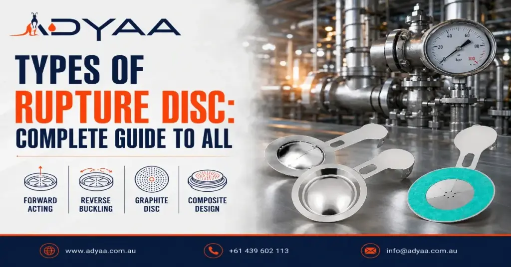
Types of Rupture Discs: Complete Guide to All Designs Pressure systems are unpredictable. When a mechanical safety valve freezes or a process reaction runs away, a rupture disc is your absolute last line of defense against a catastrophic blowout. But not all bursting discs are engineered the same way. Installing the wrong disc in a high-pulsation line or a highly corrosive chemical loop can lead to premature fatigue, nuisance bursting, or worse—total failure to relieve pressure. Understanding the different types of rupture discs is critical for plant managers, reliability engineers, and safety inspectors. In this guide, we break down the core designs, how they operate, and exactly where they belong in your facility. Quick Comparison: Major Rupture Disc Designs Disc Type Operating Ratio Fragmentation Best Application Forward-Acting Up to 80% Often fragments General pressure relief, low cost Reverse-Acting Up to 95% Non-fragmenting High-pulsation, isolating safety valves Graphite Up to 80% Fragments Highly corrosive chemical environments Core Rupture Disc Designs 1. Forward-Acting Rupture Discs (Tension Loaded) The forward-acting disc is the traditional workhorse of overpressure protection. In this design, the dome of the disc faces the process media. As pressure builds, the metal is subjected to tension. Once it hits the exact calibrated burst pressure, the metal stretches past its tensile strength and bursts outward. Operating Ratio: Typically limited to 70% to 80% of the marked burst pressure. Operating too close to the burst limit causes metal fatigue. Fragmentation: Older, solid-metal designs fragment upon bursting. However, modern scored (cross-scored) forward-acting discs open along pre-weakened lines to prevent shrapnel. Best For: General manufacturing applications and low-pulsation environments where downstream debris is not a critical concern. 2. Reverse-Acting Rupture Discs (Compression Loaded) Reverse-acting discs flip the engineering upside down. The dome faces against the process pressure. Instead of stretching the metal (tension), the process pressure pushes against the dome (compression). When the burst pressure is reached, the dome buckles and reverses, striking a knife blade or tearing along a scored line to open fully. High Operating Ratio: Because metal handles compression better than tension, these discs can operate continuously at up to 90% or 95% of their rated burst pressure without suffering fatigue. Non-Fragmenting: The buckling action allows the disc to tear open cleanly without sending metal fragments downstream. Best For: High-pulsation environments, isolating safety relief valves (no shrapnel to damage internal valve mechanics), and high-efficiency gas/liquid lines. 3. Graphite Rupture Discs When process media is heavily corrosive, standard stainless steel or Inconel discs degrade quickly, drastically altering their burst pressure. Graphite rupture discs are machined from high-purity, resin-impregnated graphite, making them immune to most acids, alkalis, and organic solvents. Corrosion Resistance: Offers superior survival in aggressive chemical and petrochemical environments. Fragmentation: Graphite is brittle and shatters upon bursting. It cannot be used directly upstream of a safety relief valve. Best For: Highly corrosive pipelines and low-pressure applications venting to a flare header or containment tank. How to Choose the Right Type of Rupture Disc Specifying the right overpressure device comes down to evaluating your specific pipeline conditions. Essential Selection Criteria 1. Operating Ratio Considerations If your normal operating pressure is very close to your maximum allowable working pressure (MAWP), you must use a reverse-acting disc. A forward-acting disc will fatigue and fail under those tight margins. 2. Downstream Fragmentation Sensitivity If you are venting into a delicate manifold or protecting a safety valve, you must use a non-fragmenting reverse-acting or scored forward-acting disc. Never use a standard solid-metal or graphite disc in these positions. 3. Media and Corrosion Resistance For standard steam, gas, or water, metallic discs are perfect. For aggressive acids like hydrochloric or sulfuric acid, graphite or exotic alloys (like Hastelloy or Tantalum) are mandatory to prevent the burst pressure from drifting due to corrosion. FAQ – Types of Rupture Discs Q: What is a rupture disc? A: A rupture disc is a non-reclosing pressure relief device that bursts at a predetermined pressure to protect industrial systems from catastrophic overpressure. Q: What is the difference between forward-acting and reverse-acting rupture discs? A: Forward-acting discs burst under tension and typically fragment, while reverse-acting discs buckle under compression, allowing for higher operating pressures without sending shrapnel downstream. Q: Can a rupture disc be used with a safety relief valve? A: Yes, but only non-fragmenting discs (like reverse-acting or cross-scored discs) should be used upstream to prevent metal fragments from jamming the safety valve internals. Q: What does the operating ratio of a rupture disc mean? A: It is the maximum allowable ratio between the system’s normal operating pressure and the disc’s marked burst pressure, usually expressed as a percentage (e.g., 80% or 95%). Q: Why use a graphite rupture disc? A: Graphite rupture discs offer extreme corrosion resistance, making them the best choice for highly aggressive chemical and petrochemical environments where metal would degrade. Q: Can you reuse a ruptured disc? A: No. Rupture discs are strictly one-time-use safety devices. Once they burst, they must be completely replaced to restore system protection. Secure Your Plant with ADYAA Pressure Relief Solutions Do not leave your plant’s safety to guesswork. Choosing between the different types of rupture discs requires precision engineering and a deep understanding of process dynamics. As a leading supplier across Australia, ADYAA provides ASME and API-compliant overpressure protection designed to keep your facility safe and operational. Consult with ADYAA Overpressure Experts Today. Rupture Disc Operating Ratio Explained (Avoid Premature Failure) Rupture Disc Operating Ratio Explained (Avoid Premature Failure) If your pressure relief devices are blowing during normal plant operations, you… Read More → Rupture Disc Selection Guide: 5 Critical Steps Rupture Disc Selection Guide: 5 Critical Steps Industrial plants cannot afford guesswork when it comes to overpressure protection. Picking a… Read More → Guide to MNSB 53 for Fabrication Guide to MNSB 53 for Fabrication: Stop Moving Heavy Steel Let’s talk about the biggest bottleneck in a heavy fabrication… Read More →