Dot Peen vs Laser Marking: Which is Best?
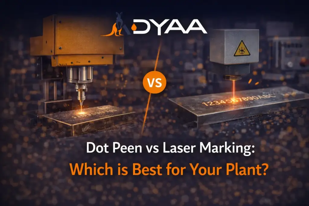
Dot Peen vs Laser Marking: Which is Best for Your Plant? In the debate of dot peen vs laser marking, the best choice depends entirely on your production environment. If you need deep, rugged marks on heavy metals that will survive sandblasting or thick painting, dot peen is the best option. If you need ultra-fast, high-contrast precision (like 2D barcodes) on delicate or high-volume parts without physical impact, laser marking is superior. Both technologies provide permanent industrial traceability, but they serve completely different manufacturing needs. Quick Comparison: Dot Peen vs Laser Marking Feature Dot Peen Marking Laser Marking Speed Moderate (Mechanical process) Extremely Fast (Speed of light) Depth Deep (Survives heavy painting & coating) Shallow (Surface-level alteration) Contrast Low (Same color as base metal) High (Dark, oxidized mark) Material Stress High (Physical impact) None (Non-contact process) Here is a comprehensive engineering breakdown to help you select the exact right system for your production line. Understanding Industrial Traceability Technologies Whether you are manufacturing aerospace components or heavy mining equipment, permanent identification is mandatory for quality control. To make an informed decision, facility managers must understand the core mechanics, benefits, and limitations of each marking system. The Mechanics of Dot Peen Marking Dot peen marking (often called pin marking) is a mechanical, contact-based process. A pneumatically or electrically driven carbide stylus repeatedly strikes the material’s surface, creating overlapping indentations to form text, numbers, or simple logos. Key Advantages Exceptional Depth: The physical indentation is deep enough to remain highly legible even after the part undergoes galvanizing or thick powder coating. Extreme Durability: It easily withstands heavy wear, tear, and long-term outdoor exposure. Budget-Friendly: These systems typically require a much lower initial capital investment than laser alternatives. Potential Trade-offs Slower Cycle Times: Because it relies on physical, mechanical movement, it cannot match the speed of a light beam. Low-contrast marks: The mark remains the same color as the base metal, making it harder for automated optical scanners to read without specialized lighting. Best Industrial Applications Marking heavy structural steel I-beams. Tracking rugged oil-and-gas pipe flanges. Identifying cast-iron engine blocks that will be heavily coated later in production. The Mechanics of Laser Marking Laser marking is a non-contact, thermal process. A machine focuses a high-intensity beam of light (typically a fiber laser for industrial metals) directly onto the material. This instantly heats, oxidizes, or vaporizes the surface. Key Advantages Unmatched Speed: Lasers can engrave complex codes and high-resolution logos in mere fractions of a second, maximizing line throughput. High Contrast: The intense heat alters the surface color. This creates a dark, high-contrast mark that barcode scanners and vision systems read instantly. No Material Stress: Because no physical tool touches the part, the laser will not warp, dent, or deform fragile components. Potential Trade-offs Surface-Level Depth: Laser marks are generally shallower than dot peen. They can be completely obscured if the part is later painted with thick industrial coatings. Higher Upfront Cost: Fiber laser technology requires a larger initial capital investment and specific optical safety enclosures. Best Industrial Applications Engraving high-density Data Matrix codes on medical devices. Etching serial numbers onto thin aerospace aluminum. Marking QR codes on delicate electronic circuit boards. Direct Comparison: Choosing the Right System To finally settle the dot peen vs laser marking debate for your facility, simply match the technology to your daily operational demands. When to Choose Dot Peen Your parts will be painted, powder-coated, or galvanized after the marking process. You are working with heavy, rugged components that face physically abusive environments. You need a highly durable, permanent mark on a strict capital budget. When to Choose Laser Marking You need to mark machine-readable codes (like 2D barcodes or QR codes) for automated tracking systems. Your production line has very fast cycle times and cannot afford bottlenecks. You are marking delicate parts, thin metals, or plastics where physical impact is strictly prohibited. Optimize Your Traceability Setup Ensuring total traceability across your production line requires precision technology. ADYAA Engineering supplies premium industrial marking systems tailored to the toughest manufacturing environments. Speak to our industrial marking experts Industrial IoT in Manufacturing Explained Industrial IoT in Manufacturing Explained Industrial IoT in manufacturing (IIoT) is the integration of smart, internet-connected sensors and cloud-based analytics… Read More → High Pressure Sealing Solutions Guide A Complete Guide to High Pressure Sealing Solutions High pressure sealing solutions are specialized industrial gaskets engineered to contain volatile… Read More → Guide to Hydrostatic Valve Testing A Complete Guide to Hydrostatic Valve Testing Hydrostatic valve testing is a mandatory, high-pressure diagnostic procedure used to verify the… Read More →
Cooling Tower Water Treatment Basics
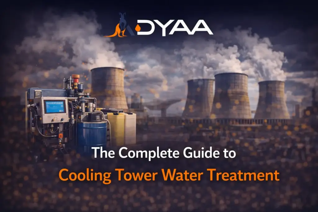
The Complete Guide to Cooling Tower Water Treatment Cooling tower water treatment is the continuous process of purifying and chemically balancing the water circulating within an industrial cooling system. Because open-loop towers constantly evaporate water, they leave behind highly concentrated minerals and capture airborne dirt, creating the perfect breeding ground for bacteria. Effective treatment uses filtration, automated blowdown, and chemical dosing to prevent mineral scale buildup, inhibit metallic corrosion, and stop the growth of dangerous biological pathogens like Legionella. Without a strict treatment protocol, heat transfer efficiency plummets, energy bills skyrocket, and the facility becomes a severe public health risk. Quick Overview: Cooling Tower Threats & Solutions Operational Threat Impact on the System Required Treatment Solution Mineral Scaling Insulates heat exchangers, drops thermal efficiency Scale inhibitors & automated blowdown System Corrosion Eats away metal piping, causes catastrophic leaks Corrosion inhibitors & strict pH control Biological Fouling Spreads Legionella, creates an insulating biofilm Oxidizing & non-oxidizing biocides Airborne Debris Creates sludge in the basin, clogs system filters Side-stream physical filtration Here is an engineering breakdown of the core components required to protect your thermal infrastructure. The 3 Major Threats to Your Cooling Tower If not treated, circulating water can damage your cooling system internally through three major mechanisms. 1. Mineral Scaling As water evaporates, minerals such as calcium and magnesium concentrate and deposit onto hot heat exchanger surfaces. Scale acts as a powerful thermal insulator. It severely reduces the plant’s heat transfer efficiency, forcing fans and chiller pumps to work much harder to achieve the same cooling effect. 2. System Corrosion Imbalanced pH levels and highly oxygenated water eat away at metallic piping, chiller tubes, and structural supports. Localized pitting corrosion can rapidly eat through steel components. This leads to catastrophic water leaks and premature equipment failure that halts production. 3. Biological Fouling Warm, nutrient-rich cooling water exposed to sunlight is the ideal environment for algae, biofilm, and deadly Legionella bacteria. Biofilm acts as an even stronger insulator than mineral scale. Furthermore, biological fouling accelerates localized under-deposit corrosion, destroying metal beneath the slime layer. The 4 Pillars of Effective Cooling Tower Water Treatment A robust cooling tower water treatment program requires a multi-layered approach to address physical, chemical, and biological threats simultaneously. 1. Physical Filtration (Side-Stream Filters) Before adding expensive chemicals, you must remove the dirt, dust, and rust that the tower has scrubbed from the ambient air. How it works: Side-stream filtration continuously pulls a small percentage of the circulating water through highly efficient sand or screen filters. The Benefit: Removing suspended solids prevents thick sludge buildup in the cooling tower basin and reduces the total amount of chemical biocides required. 2. Biological Control (Biocides) Controlling biological growth is a strict legal and health requirement to prevent outbreaks of Legionnaires’ disease. Oxidizing Biocides: Chemicals like chlorine or bromine are dosed continuously to quickly kill free-floating bacteria and algae in the water. Non-Oxidizing Biocides: These are dosed periodically (“shock dosed”) to penetrate and destroy stubborn biofilms clinging to the tower’s plastic fill media. 3. Chemical Inhibitors (Scale & Corrosion) To protect the structural integrity of your expensive heat exchangers, specific chemical formulations must be continuously injected into the water. Scale Inhibitors: These chemicals alter the microscopic structure of mineral crystals, keeping them suspended in the water so they cannot stick to hot metal surfaces. Corrosion Inhibitors: These create a microscopic, sacrificial protective film on the internal metal surfaces, shielding the raw steel from acidic water and dissolved oxygen. 4. Automated Blowdown (Bleed-Off) As water evaporates, the remaining water becomes dangerously concentrated with dissolved solids and hardness. The Solution: An automated conductivity controller monitors the water 24/7. When mineral concentration gets too high, the system automatically opens a “blowdown” valve to dump the dirty water down the drain, simultaneously replacing it with fresh, clean “makeup” water. Routine Monitoring and Compliance Installing a treatment system is never a “set and forget” process. Maintaining thermal efficiency requires active monitoring: Daily/Weekly: Check chemical dosing pump levels and verify automated controller readings (pH, ORP, and conductivity). Monthly: Conduct independent laboratory testing for Legionella and total microbial counts as mandated by local health authorities. Annually: Perform a full physical inspection of the tower fill media, drift eliminators, and basin for hidden biofilm or stubborn scale deposits. Optimize Your Thermal Management Poor water quality destroys cooling towers and wastes massive amounts of operational energy. ADYAA’s thermal engineering team delivers expert cooling tower inspections, structural upgrades, and advanced water treatment solutions to ensure peak system efficiency. Request a cooling tower audit today Industrial IoT in Manufacturing Explained Industrial IoT in Manufacturing Explained Industrial IoT in manufacturing (IIoT) is the integration of smart, internet-connected sensors and cloud-based analytics… Read More → High Pressure Sealing Solutions Guide A Complete Guide to High Pressure Sealing Solutions High pressure sealing solutions are specialized industrial gaskets engineered to contain volatile… Read More → Guide to Hydrostatic Valve Testing A Complete Guide to Hydrostatic Valve Testing Hydrostatic valve testing is a mandatory, high-pressure diagnostic procedure used to verify the… Read More →
Laser Marking Machine vs Dot Peen Guide
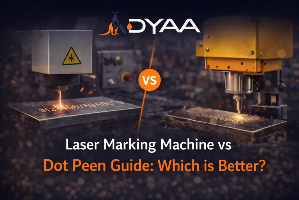
Laser Marking Machine vs Dot Peen Guide: Which is Better? When engineering a traceability process for your facility, the debate between a laser marking machine and a dot peen system comes down to one absolute rule: match the physics of the machine to the realities of your production line. If you need ultra-fast, high-contrast, non-contact precision for barcodes, a laser marking machine is superior. If you are marking heavy cast iron that will be sandblasted and hot-dip galvanized, a dot peen marking machine is the only technology that will survive. As a leading supplier in Australia, ADYAA distributes both specialized laser marking machines and dot peen marking machines. We do not rely on guesswork; we engineer permanent traceability solutions that guarantee your plant remains compliant with global industrial standards. Quick Comparison: Laser Marking vs Dot Peen Technologies Feature Laser Marking Machine Dot Peen Marking Machine Primary Process Non-contact thermal oxidation Mechanical physical impact Marking Speed Extreme (Fractions of a second) Moderate Mark Depth Surface-level to shallow Deep (Survives heavy coatings) Contrast High (Perfect for 2D Barcodes) Low (Matches base material color) Consumables Zero Carbide Stylus What Is a laser marking machine? A laser marking machine is a high-speed, non-contact industrial system that uses a focused beam of light to alter the surface of a material. Powered by a high-intensity source (such as a Fiber, UV, or CO2 laser), the machine instantly heats, oxidizes, or vaporizes the substrate to create permanent alphanumeric text, high-density 2D Data Matrix codes, and high-resolution logos. Because no physical tool ever touches the part, the process causes zero mechanical stress, making it the premier choice for everything from delicate electronics to hardened aerospace alloys. Benefits of a Quality laser marking machine Integrating a premium optical marking system into your factory floor completely transforms your traceability speed and accuracy: Unmatched Production Speed: Lasers operate at the speed of light. They can etch complex, machine-readable codes in milliseconds, eliminating bottlenecks on high-volume automated lines. Maximum Contrast & Readability: The thermal process creates a dark, highly contrasted oxidation layer. This guarantees a 100% first-pass read rate when scanned by automated vision systems and barcode readers. Zero Consumables: Unlike inkjet printers that require expensive fluids or dot peen systems that wear out mechanical styluses, a laser marking machine runs purely on electricity, drastically reducing your long-term operational expenditure (OpEx). The Dot Peen Alternative: When You Need Extreme Depth While a laser marking machine dominates in speed and contrast, you must understand its limitations. A laser mark is generally a surface-level alteration. If you are manufacturing structural steel beams, heavy mining equipment, or automotive chassis in Australia, your parts will likely undergo aggressive post-processing—such as sandblasting, heavy powder coating, or galvanization. These processes will completely erase a laser mark. In these harsh environments, a dot peen marking machine is required to gouge deep physical indentations into the metal that remain legible through the thickest industrial coatings. How to Choose the Best laser marking machine vs Dot Peen Stop wasting capital on the wrong technology. As a specialist supplier, ADYAA ensures you select the correct system based on strict operational data. Evaluate these critical factors: Automated Scanning Requirements: If your supply chain relies on automated optical scanners to read QR codes or Data Matrix codes, you must choose a laser marking machine for its high contrast. Post-Marking Surface Treatments: If the part will be painted or galvanized after it is marked, you must choose a dot peen marking machine for its physical depth. Material Fragility: If you are marking thin-walled aluminum, medical plastics, or delicate PCB boards, the mechanical impact of a dot peen stylus will shatter or warp the part. A non-contact laser is mandatory. Common Mistakes When Buying a laser marking machine Purchasing optical equipment without a technical strategy is a costly rookie mistake. Here are the most common errors and exactly how ADYAA solves them: 1. Buying the Wrong Laser Source for the Material The Mistake: Purchasing a standard Fiber laser to mark organic materials like wood or transparent plastics. The light will pass right through or burn the material uncontrollably. The Solution: ADYAA provides strict onsite material testing to match the exact wavelength to your substrate—supplying CO2 lasers for organics, UV lasers for cold-marking sensitive plastics, and Fiber lasers for industrial metals. 2. Ignoring Environmental Hazards The Mistake: Installing an unprotected open-source laser marking machine in a dusty fabrication shop, leading to ruined optical lenses and severe safety hazards for workers. The Solution: ADYAA distributes fully enclosed, Class 1 safety-rated laser workstations equipped with industrial fume extractors to protect your staff and your equipment. 3. Overlooking Deep Coating Requirements The Mistake: Buying an expensive laser to mark steel pipes, only to watch the mark disappear completely when the pipe is painted black. The Solution: For heavy coatings, we steer our clients away from lasers entirely and supply our high-pressure pneumatic dot peen systems to ensure the ID survives the paint. FAQ – laser marking machine Q: Can a laser marking machine cut through metal? A: No. While they operate on similar principles, a marking laser uses lower wattage (typically 20W to 100W) designed to alter the surface, whereas a cutting laser uses massive wattage (1,000W+) to slice entirely through the material. Q: Are there safety concerns with laser marking? A: Yes, direct exposure to a raw laser beam can cause severe eye damage. That is why reputable suppliers ensure all industrial systems are housed in Class 1 safety enclosures with specialized optical viewing glass. Q: Do I need a computer to run the machine? A: Most modern systems come with integrated industrial PCs or user-friendly touchscreen controllers loaded with software to easily generate serial numbers, barcodes, and logos. Conclusion Do not leave your plant’s traceability to chance. As a dedicated distributor and supplier of industrial equipment, ADYAA provides the most advanced laser marking machines and dot peen marking machines in the country. From the heavy manufacturing sectors of Sydney to the remote mining operations of Perth, our
Guide to Industrial Marking Systems
The Ultimate Guide to Industrial Marking Systems Industrial marking systems are the foundational tools used in modern manufacturing to create permanent, traceable identification on parts and products. As a leading distributor in Australia, ADYAA provides advanced marking solutions—including dot peen marking machines and laser marking machines—designed to meet strict ISO and industry-specific compliance standards. Selecting the right technology is critical: while laser marking offers unmatched speed for high-volume lines, dot peen marking remains the gold standard for deep, structural identification on rough surfaces and post-processed metals. Quick Comparison: Marking Technologies Distributed by ADYAA Feature Dot Peen Marking Machine Laser Marking Machine Primary Process Mechanical Indentation Thermal Light Beam Best Material Heavy Metals, Castings, Rough Steel Metals, Plastics, Ceramics Mark Depth Deep (Visible after painting) Surface to Moderate Contrast Low (Material color) High (Dark/Oxidized) Consumables Carbide Stylus (Long life) None What Is a Marking System? A marking system is an industrial machine engineered to engrave, etch, or print permanent identifiers—such as serial numbers, 2D Data Matrix codes, and company logos—directly onto a product or component. These systems act as the digital link between a physical part and its manufacturing data, ensuring that every item can be tracked from the assembly line to the end user. In the modern era of Industrial IoT, a robust marking system is the first step toward a fully digitized supply chain. Why ADYAA is the Preferred Supplier in Australia As a specialist supplier, ADYAA distributes high-performance industrial marking systems across Australia, ensuring local businesses have access to global-standard traceability. Local Expertise: We provide on-ground support and technical analysis to match the right machine to your production environment. Comprehensive Portfolio: From portable handheld units to fully integrated robotic cells, we cover every marking requirement. Industrial Reliability: Our machines are engineered for the harsh conditions of the mining, oil & gas, and heavy manufacturing sectors. Understanding the Two Pillars of Permanent Marking To optimize your facility, you must understand the mechanics of the two primary systems distributed by ADYAA. 1. The Dot Peen Marking Machine A dot peen marking machine (often called a pin marker) uses a pneumatically or electrically driven carbide stylus to physically indent the material’s surface. The Durability Factor: Because the mark is an actual physical indentation, it remains legible even after the part is galvanized, powder-coated, or subjected to heavy industrial wear. ADYAA Solution: We offer the MNSB series, ranging from battery-operated portable units to high-pressure deep markers for the toughest steels. 2. The Laser Marking Machine A laser marking machine is a non-contact, high-speed solution that uses a focused beam of light to alter the surface of the material. The Precision Factor: Lasers deliver ultra-high resolution, making them perfect for complex logos and high-density 2D Data Matrix codes. ADYAA Solution: Our Fiber Laser systems provide high-contrast marks on both metallic and non-metallic substrates without the need for inks or solvents. Benefits of a Quality Marking System Investing in a premium marking setup transforms your production line operations: Absolute Traceability: Instantly trace a defective part back to its specific batch, machine, and operator. Counterfeit Prevention: Permanent, high-resolution logos protect your brand integrity in the global market. Error Elimination: Automated scanning of machine-readable codes eliminates manual data entry errors on the factory floor. How to Choose the Best Marking System Choosing the right technology requires matching the physics of the process to your specific operational demands: Post-Processing: Choose a dot peen marking machine if your parts undergo sandblasting or thick painting after the mark is applied. Speed & Readability: Choose a laser marking machine if you require high-speed serialization and machine-readable barcodes for automated tracking. Material Sensitivity: Use non-contact lasers for delicate parts and mechanical dot peen for rugged, heavy-duty metals. Common Mistakes When Buying a Marking System Many facilities invest in the wrong technology due to a lack of technical foresight. Here are common pitfalls and how ADYAA solves them: 1. Ignoring Post-Marking Surface Coatings The Mistake: Buying a shallow laser marker for a part that will later receive a thick powder coat, rendering the mark invisible. The ADYAA Solution: We provide Deep-Pneumatic Dot Peen systems specifically designed to create indentations deep enough to remain legible through heavy industrial coatings. 2. Underestimating Production Cycle Times The Mistake: Purchasing a slower mechanical marker for a high-volume line, creating a severe bottleneck. The ADYAA Solution: ADYAA supplies High-Wattage Fiber Lasers that can mark parts in fractions of a second, keeping your production line moving at maximum speed. 3. Neglecting Asset Portability The Mistake: Buying only stationary machines for a plant that needs to mark large, immobile assets like pipes or chassis. The ADYAA Solution: We distribute Wireless, Battery-Operated Handheld Markers that allow your operators to bring the marking system directly to the asset. 4. Choosing the Wrong Technology for the Substrate The Mistake: Using a thermal laser on a heat-sensitive plastic, causing melting or warping. The ADYAA Solution: Our engineers provide onsite material testing to determine whether a Fiber, UV, or CO2 laser—or a mechanical system—is the safe choice for your specific material. FAQ – Marking System Q: Which marking system is the fastest? A: A laser marking machine is the fastest technology, capable of engraving complex codes in fractions of a second. Q: What is the best system for parts that will be painted? A: A dot peen marking machine is ideal, as it creates deep physical indentations that remain legible through heavy coatings and galvanization. Q: Does ADYAA provide portable solutions? A: Yes, we distribute a wide range of handheld, battery-powered industrial marking systems for heavy-duty field use across Australia. Secure Your Traceability with ADYAA Australia Don’t leave your part identification to chance. As a dedicated distributor and supplier of industrial marking systems, ADYAA ensures your plant stays compliant and efficient. From Perth to Sydney, our team provides the equipment and technical support needed to secure your critical infrastructure. Explore ADYAA Marking Systems Laser Marking Machine vs Dot Peen Guide Laser Marking Machine vs Dot Peen Guide: Which is Better? When engineering a
Best Dot Peen Machine for Heavy Metals
How to Choose the Best Dot Peen Machine for Heavy Metals The best dot peen machine for heavy metals depends entirely on your required marking depth and facility setup. For extreme depth on hard steel that must survive sandblasting and galvanization, a pneumatic dot peen marking machine is the absolute best choice. If you require high-precision marking, portability, and do not have access to a compressed air line, an electromagnetic dot peen marking machine is the superior option. As a premier supplier in Australia, ADYAA distributes both specialized dot peen marking machines and laser marking machines to ensure heavy industries achieve permanent, compliant part traceability. Here is a comprehensive engineering breakdown to help you select the exact right system for your heavy metal applications. Quick Comparison: Pneumatic vs. Electromagnetic Dot Peen Feature Pneumatic Dot Peen Machine Electromagnetic Dot Peen Machine Power Source Compressed Air + Electricity Electricity Only (Plug & Play or Battery) Marking Depth Extreme (Up to 1.0mm+ on steel) Moderate to Deep (Up to 0.5mm) Best Substrate Cast iron, structural steel, alloys Aluminum, mild steel, hard plastics Post-Processing Survives heavy paint & galvanizing Survives light to medium coatings Portability Limited (tethered to air lines) High (Battery-powered handhelds available) What Is a dot peen marking machine? A dot peen marking machine is a heavy-duty industrial traceability tool that uses a pneumatically or electrically driven carbide (or diamond-tipped) stylus to strike a material’s surface. Operating at high frequencies, the stylus creates overlapping micro-indentations (dots) to form permanent serial numbers, alphanumeric text, logos, and 2D Data Matrix codes. Because it physically displaces the metal rather than burning it, dot peen is widely considered the most rugged marking technology available for heavy industry. Benefits of a Quality dot peen marking machine Integrating a premium dot peen system into your production line offers distinct advantages over other marking methods: Unmatched Mark Survivability: The deep physical indentations remain perfectly readable even after harsh post-processing treatments like hot-dip galvanizing, sandblasting, and thick powder coating. Cold Marking Process: Unlike lasers, dot peen is a mechanical, non-thermal process. It does not introduce heat into the substrate, meaning it will not alter the metallurgical properties or warp the metal. Cost-Effective Operations: These machines do not require expensive inks, solvents, or high power consumption. The only consumable is the rugged metal stylus, which has an incredibly long operational lifespan. Why Heavy Metals Require Dot Peen Technology Heavy industrial manufacturing—such as mining equipment fabrication, oil & gas pipeline construction, and structural steel manufacturing—presents unique traceability challenges. While a laser marking machine is incredibly fast and perfect for high-contrast barcodes, the mark it leaves is typically a surface-level oxidation. When heavy metals undergo harsh post-processing environments, surface marks are instantly destroyed. The best dot peen machine solves this by physically driving the stylus into the metal. Because the metal is physically displaced, the mark remains perfectly legible even after decades of outdoor corrosion in the harsh Australian outback. Types of Dot Peen Machines Distributed in Australia To ensure your production line operates without bottlenecks, you must select the correct form factor for your specific workflow. ADYAA supplies three primary configurations of the best dot peen machine technologies across Australia. 1. Column-Mounted (Benchtop) Dot Peen Machines These are stationary units bolted to a workbench on the factory floor. How They Work: The operator brings the metal component to the machine. A motorized Z-axis column lowers the marking head precisely onto the part. Best Application: High-volume batch marking of smaller, maneuverable heavy metal components like engine valves, gears, metal tags, and machined pipe fittings. 2. Portable Handheld Dot Peen Machines For heavy industry, bringing the part to the machine is often impossible. How They Work: These lightweight, pistol-grip units are carried directly to the asset. Operators simply press the marking window against the metal and pull the trigger. Best Application: Marking massive structural I-beams, oversized oil flanges, heavy casting molds, and automotive chassis (VIN marking). 3. Integrated (Custom) Dot Peen Systems These are headless marking units designed to be bolted directly into an automated production line or robotic cell. How They Work: Controlled entirely by the plant’s central PLC, these units automatically stamp parts as they move down a conveyor belt. Best Application: 24/7 automated automotive manufacturing and high-throughput metal fabrication. How to Choose the Best dot peen marking machine Choosing the right machine requires aligning your facility’s infrastructure with your specific traceability goals. As a leading supplier, ADYAA recommends evaluating your plant’s air supply, the size of your parts, and the hardness of your metal. Core Specifications to Look For 1. Stylus Hardness (Rockwell Hardness – HRC) The stylus is the only consumable in a dot peen system. If you are marking hardened tool steel or titanium (up to 62 HRC), you must ensure the machine is equipped with a high-grade tungsten carbide or custom diamond-tipped stylus to prevent rapid wear. 2. X/Y Axis Window Size The marking window dictates the maximum size of the text or logo you can print in a single operation. A standard window is 100mm x 50mm, but heavy pipe fabricators often require larger 150mm x 100mm windows to fit multi-line specifications and API logos. 3. Software Connectivity A modern dot peen marking machine is useless if it cannot communicate with your database. The best systems feature built-in Wi-Fi, Ethernet, and RS232 ports, allowing them to pull serial numbers directly from your ERP system, eliminating the risk of operators typing the wrong ID. Common Mistakes When Buying a Dot Peen Marking Machine Investing in heavy-duty marking equipment without expert guidance can lead to costly workflow bottlenecks. Here are common errors and how ADYAA resolves them: 1. Buying an Electromagnetic Machine for Deep Galvanizing The Mistake: Purchasing an electric machine to mark steel pipes that will later be heavily hot-dip galvanized. The shallow mark fills with zinc and becomes invisible. The Solution: ADYAA supplies high-pressure Pneumatic Dot Peen systems specifically designed to gouge deep enough into heavy steel to survive the thickest industrial coatings. 2. Limiting Mobility
O-Ring Material Selection for Harsh Environments
O-Ring Material Selection for Harsh Environments A failing O-ring is an industrial plant manager’s worst nightmare. When operating under extreme heat, aggressive chemicals, or massive pressure, standard rubber simply melts away or shatters. Mastering O-Ring Material Selection for Harsh Environments is critical for preventing catastrophic blowouts, toxic leaks, and expensive unplanned downtime. As we discussed in our recent guide on Choosing Gasket Materials for Chemical Resistance, your sealing components carry the massive responsibility of keeping your facility safe. Here is how to match the right high-performance elastomer to your most extreme operating conditions. The 3 Destroyers of Standard O-Rings You cannot rely on general-purpose seals like basic Nitrile when pushing your systems to the limit. Proper O-Ring Material Selection for Harsh Environments requires defending against three primary forces: Thermal Degradation: Extreme heat cooks standard elastomers, causing them to permanently harden and crack. Extreme cold causes them to shrink and lose their critical flexibility. Chemical Attack: Aggressive solvents, strong acids, and caustic bases will dissolve incompatible O-rings from the inside out. Pressure Extrusion: High system pressure literally forces the soft O-ring material out of its designated groove, breaking the seal entirely. Top Elastomers for Extreme Conditions To survive harsh industrial applications, engineers rely on a specific tier of advanced compounds. FFKM (Kalrez®): The ultimate heavy-duty choice. It offers near-universal chemical resistance and survives continuous temperatures up to 327°C. FKM (Viton®): The industry standard for aggressive environments. It handles high temperatures, petroleum oils, fuels, and many harsh chemicals. PTFE (Teflon™): Completely inert to almost all chemicals. However, because it is a rigid plastic rather than a flexible rubber, it often requires an encapsulated design (a rubber core wrapped in PTFE) to maintain a tight seal. Silicone: The go-to choice for extreme temperature fluctuations, particularly in extreme cold (down to -100°C), though it lacks strong chemical resistance against oils. Real-World Example: Australian Mining Operations Consider an Australian mining facility dealing with heavy-duty hydraulic equipment. The equipment operates outdoors in extreme heat, utilizing aggressive hydraulic fluids under massive pressure. Standard seals deteriorate rapidly here. By prioritizing accurate O-Ring Material Selection for Harsh Environments and upgrading to high-durometer FKM (Viton) seals, the facility prevents fluid degradation and pressure extrusion simultaneously. This keeps the machinery running and prevents hazardous leaks into the surrounding environment. Integrating Seals with System Safety High-performance O-rings are only one part of the safety equation. If your system pressure spikes uncontrollably, even the strongest FFKM seal will eventually fail. This is why your sealing strategy must be paired with accurate Sizing Relief Valves for Industrial Facilities. By ensuring your pressure relief devices vent dangerous spikes immediately, you protect your O-rings from enduring forces beyond their design limits. People Also Ask (FAQs) Q: What is the best O-ring material for extremely high temperatures? A: FFKM (Kalrez) is generally the best choice for extreme heat, capable of maintaining its seal in environments exceeding 300°C. Q: Can I use Silicone O-rings in hydraulic systems? A: No. While Silicone is excellent for temperature extremes, it has very poor resistance to petroleum-based oils and hydraulic fluids. FKM (Viton) or Nitrile are better choices. Q: Why do O-rings extrude under high pressure? A: Extrusion happens when the pressure is too high for the O-ring’s hardness (durometer), or the clearance gap in the hardware is too large. Using a harder material or adding backup rings prevents this. The Bottom Line You cannot compromise when sealing aggressive industrial fluids. Strategic O-Ring Material Selection for Harsh Environments is an investment in your plant’s operational uptime and environmental safety. By evaluating the specific chemical makeup, temperature range, and pressure limits of your system, you can eliminate recurring leaks and equipment damage. Get Expert Sealing Solutions Don’t let a miscalculated seal cause your next shutdown. If you are struggling with chronic leaks or premature component failure, reach out to the ADYAA Engineering Team today for expert sizing, material selection, and support tailored for the Australian industrial sector. O-Ring Material Selection for Harsh Environments O-Ring Material Selection for Harsh Environments A failing O-ring is an industrial plant manager’s worst nightmare. When operating under extreme… Read More → Mechanical Seal Failure Causes & Prevention Mechanical Seal Failure Causes & Prevention A leaking pump is a massive liability. When fluid escapes along a rotating shaft,… Read More → Industrial Sealing Systems Prevent Leakage Failures Industrial Sealing Systems Prevent Leakage Failures A minor drip in a high-pressure line is never just a drip. It is… Read More →