How to Size a Pressure Relief Valve: Key Factors Engineers Must Consider
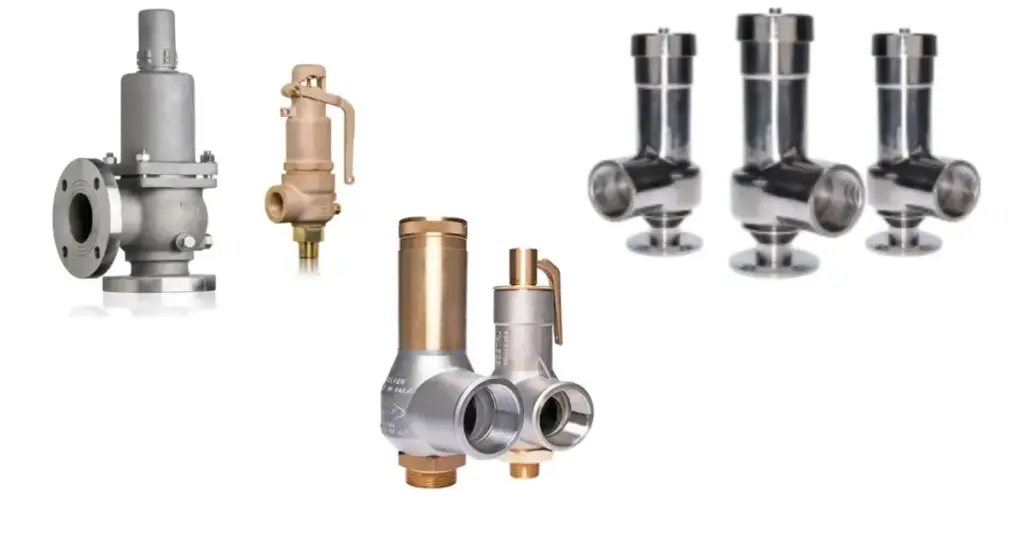
How to Size a Pressure Relief Valve: Key Factors Engineers Must Consider In process engineering, “bigger” is not always better. When you need to Size a Pressure Relief Valve , the stakes are incredibly high. Undersize the valve: It won’t release pressure fast enough, leading to potential vessel rupture or explosion. Oversize the valve: It will open, release too much pressure too quickly, slam shut, and then pop open again. This is called Valve Chatter, and it can destroy the valve seat and piping in seconds. Sizing isn’t just about picking a pipe size that matches your tank nozzle. It is a precise calculation governed by codes like ASME Section VIII and API 520. ADYAA supplies, engineering team that supports clients with complex sizing scenarios every day. Below, we break down the 4 critical steps you must follow to correctly Size a Pressure Relief Valve for your application. 1. Establish the Set Pressure (and MAWP) The first number you need is the MAWP (Maximum Allowable Working Pressure) of the vessel you are protecting. Your Set Pressure (the point where the valve starts to open) must never exceed the MAWP. Rule of Thumb: Most engineers set the relief valve at exactly the MAWP. Operating Margin: You need a gap between your normal operating pressure and the set pressure. If they are too close (e.g., operating at 95 bar with a set pressure of 100 bar), the valve will “simmer” or leak constantly. Aim for a 10% differential. Key takeaway: To correctly Size a Pressure Relief Valve, ensure your normal operating pressure is at least 10% below the set pressure to prevent nuisance leakage. 2. Determine the Required Relieving Capacity This is the most difficult step. You must ask: “What is the worst-case scenario?” You don’t size a valve for normal flow; you size it for the catastrophe. Common scenarios include: Blocked Discharge: A valve downstream closes inadvertently while pumps are running. External Fire: Fire heats the tank, causing the liquid inside to boil and expand rapidly. Thermal Expansion: A pipe full of liquid heats up in the sun. You must calculate exactly how much fluid (kg/hr or L/min) needs to escape to keep the pressure from rising more than 10% or 21% above the MAWP (depending on the code). 3. Identify the Fluid State (Gas vs. Liquid) The physical state of the medium dictates the valve design and the formula used to Size a Pressure Relief Valve. Gas/Steam (Compressible): You are dealing with volume expansion. You need a valve with a “Pop” action for rapid release. The sizing formula relies heavily on the gas temperature and molecular weight. Liquid (Incompressible): You are dealing with hydraulic pressure. You need a standard Relief Valve. Sizing is based on viscosity and specific gravity. The Trap: Be careful with Two-Phase Flow (mixture of gas and liquid). This requires complex sizing calculations (API 520 Part I) because the gas expands while the liquid drags, creating a “choking” effect in the nozzle. 4. Account for Backpressure Where does the fluid go when the valve opens? Atmosphere: If it vents to open air, backpressure is usually zero. Header System: If it vents into a long pipe shared by other valves, there is “Backpressure” pushing back against the valve. Why it matters: Standard safety valves are affected by backpressure. If the backpressure in the discharge pipe varies by more than 10% of the set pressure, it will force the valve to stay closed when it should open. To properly Size a Pressure Relief Valve in a closed loop, you may need a Balanced Bellows design (which shields the spring from backpressure) or a Pilot-Operated Valve. Conclusion: Precision is Safety There is no room for guesswork. A valve that is sized incorrectly is a liability, not a safeguard. To Size a Pressure Relief Valve correctly, you need accurate data: MAWP, worst-case flow scenarios, fluid properties, and backpressure data. ADYAA, we don’t just sell valves; we verify the application. Our engineers can help you review your process conditions to ensure the valve you buy is the valve that will save your plant. Need sizing support? Browse ADYAA Pressure Relief Valves Contact our Engineering Team today. How Industrial Automation Sensors Improve Automation & Efficiency in Manufacturing How Industrial Automation Sensors Improve Automation & Efficiency in Manufacturing In modern manufacturing, efficiency, accuracy, and reliability are more important… Read More → How Vision & Imaging Sensors Transform Automated Inspection Systems How Vision & Imaging Sensors Transform Automated Inspection Systems Maintaining product quality while keeping up with high-speed production is crucial…. Read More → IoT and Automation in Industrial Operations: Boost Efficiency, Safety, and Reliability IoT and Automation in Industrial Operations: Boost Efficiency, Safety, and Reliability Discover how IoT and automation revolutionize industrial operations. Improve… Read More →
Decoding the Datasheet: The Truth About Pressure Transmitter Accuracy
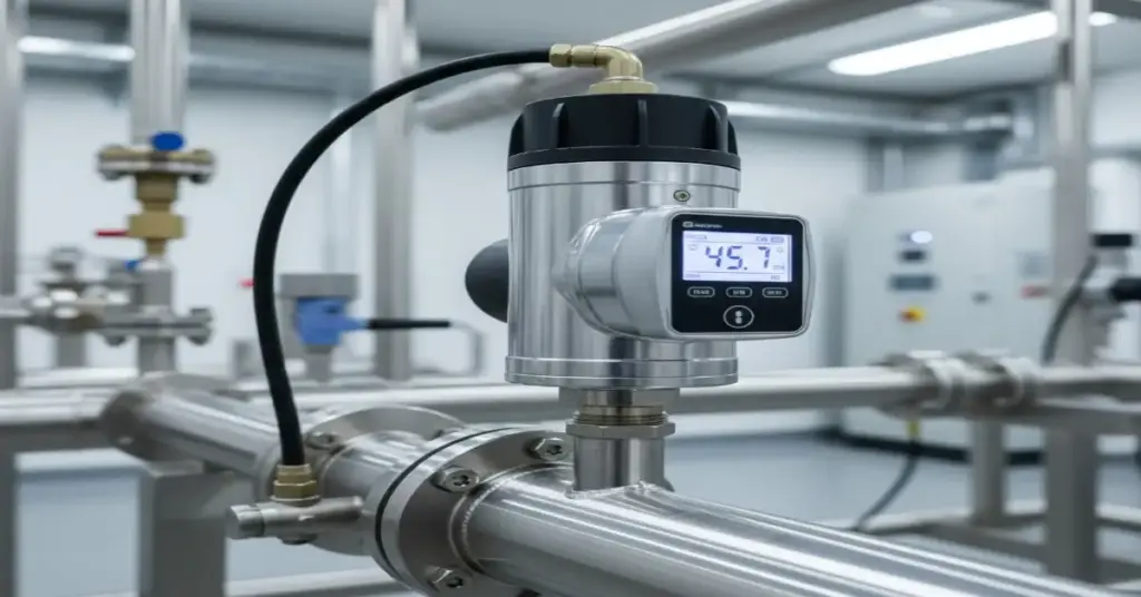
Decoding the Datasheet: The Truth About Pressure Transmitter Accuracy In the world of Industrial Pressure Sensors, “Accuracy” is the most expensive word on the datasheet. You see a shiny number like “±0.075%” printed in bold, and it’s natural to assume that’s exactly the error margin you’ll see on your control screen. But once you install that transmitter in the field—where it’s vibrating on a pump or baking in the Australian sun—the reality can be very different. This confusion leads to two common (and costly) mistakes: Over-specifying: Buying a Ferrari-level sensor for a go-kart application (wasting money). Under-specifying: Buying a cheap sensor that drifts constantly, ruining your process control. ADYAA, we believe the best customer is an educated one. So, let’s peel back the layers of the datasheet and explain what those accuracy specs actually mean for your plant. 1. The “Lab Number”: What Reference Accuracy Really Means The first number you see on a datasheet (e.g., ±0.075% of Span) is called Reference Accuracy. Think of this as the “Showroom Condition.” It tells you how the sensor performs in a perfect, air-conditioned laboratory with stable pressure and zero vibration. It is calculated using three specific test criteria, known as the “Big Three”: A. Linearity (The Straight Line) If you graph pressure vs. output signal, it should be a perfectly straight diagonal line. Linearity measures how much the sensor “wobbles” off that perfect path. If the linearity is bad, your DCS might say the tank is 50% full when it’s actually 51%. B. Hysteresis (The Memory Effect) Sensors have “muscle memory.” Going Up: You pressurize to 10 bar, and it reads 10.01 bar. Coming Down: You depressurize back to 10 bar, and it reads 9.99 bar. That difference is Hysteresis. It happens because the metal sensing diaphragm doesn’t snap back perfectly instantly. C. Repeatability (The Most Important Spec) If you hit the sensor with exactly 5 bar of pressure ten times in a row, does it give you the exact same number ten times? Repeatability is king. Even if a sensor is slightly off, if it’s repeatable, you can calibrate it to be perfect. If it’s not repeatable, it’s untrustworthy. The Reality Check: Reference Accuracy only tells you how good the sensor can be. It doesn’t tell you how good it will be in your plant. 2. The Real World: Why Accuracy Drops in the Field Your plant isn’t a laboratory. It’s hot, noisy, and dirty. These environmental factors introduce new errors that are not included in that headline “0.075%” number. Temperature Effect (The Sun Factor) Liquids expand when they get hot. Inside a Pressure Transmitter, there is a tiny amount of oil that transfers pressure to the sensor. The Problem: If your transmitter sits in the 40°C afternoon sun and then cools down to 10°C at night, that internal oil expands and contracts. This causes the “Zero” point to drift. The Fix: High-quality sensors use “Active Temperature Compensation” to mathematically correct this error in real-time. Cheap sensors do not. Static Pressure Effect This is a big one for Differential Pressure (DP) flow measurement. If you are measuring a tiny pressure drop across an orifice plate, but the pipe itself is pressurized to 50 bar, that massive static pressure squeezes the sensor body. This physical stress shifts the reading. 3. The https://www.google.com/search?q=%231 Mistake: ignoring “Turndown Ratio” This is the most common reason we see “accurate” sensors giving bad data. Turndown Ratio is how much of the sensor’s range you are actually using. Accuracy is usually a percentage of the Maximum Range, not your calibrated set point. Scenario: You buy a sensor rated for 0-100 bar. The Mistake: You only use it to measure 0-5 bar. The Result: That tiny error margin at 100 bar becomes a huge error margin when you are only looking at 5 bar. Engineer’s Tip: Always buy a sensor range that is closest to your actual operating pressure. Don’t buy a 100 bar sensor to measure 5 bar “just in case.” 4. The “Real” Number: Total Probable Error (TPE) If you want to know the honest accuracy of a device, you need to calculate the Total Probable Error (TPE). This isn’t usually printed on the datasheet, but it’s the number that matters. It combines the Lab Accuracy with the Temperature and Static Pressure effects. Standard Sensor: Might claim 0.075% accuracy, but the real TPE is 0.25%. High-End Sensor: Might claim 0.04% accuracy, and the real TPE is 0.10%. Why does this matter? If you are calculating the efficiency of a million-dollar boiler, that difference is massive. 5. Which Sensor Tier Do You Actually Need? At ADYAA, we help you save money by matching the right tier to the right job. You don’t need a Porsche to drive to the grocery store. Tier 1: Standard Industrial (±0.25% – ±0.5%) Use for: Monitoring pumps, water tank levels, compressed air lines. Why: You just need to know if the pressure is stable. Close enough is good enough. Tier 2: Precision Process (±0.075%) Use for: Chemical reactors, steam flow, critical control loops. Why: A small error here could ruin a batch or waste energy. Tier 3: High Performance (±0.04% or better) Use for: Custody transfer (selling oil/gas), leak testing, calibration labs. Why: When every drop of product equals money, you pay for the best. Final Thoughts Don’t let the specs intimidate you. Understanding Pressure Transmitter Accuracy is simply about matching the tool to the environment. ADYAA, supplies, we don’t just ship boxes. Our engineering team can help you calculate the Total Probable Error for your specific application, ensuring you get a sensor that is accurate enough to keep you safe, without blowing your maintenance budget. Need help selecting the right pressure transmitter? Explore the ADYAA Pressure Range Contact us for a TPE Calculation. How Industrial Automation Sensors Improve Automation & Efficiency in Manufacturing How Industrial Automation Sensors Improve Automation & Efficiency in Manufacturing In modern manufacturing, efficiency, accuracy, and reliability are more important… Read More → How Vision & Imaging Sensors
Understanding Australian Standards for Industrial Pressure Safety Systems
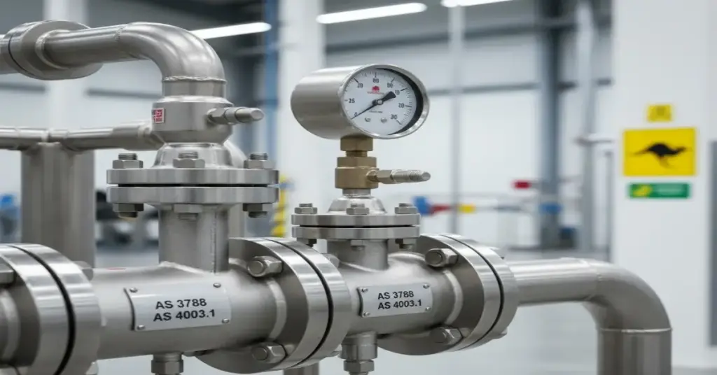
Understanding Australian Standards for Industrial Pressure Safety Systems In the Australian industrial sector, the phrase “She’ll be right” doesn’t apply to pressure vessels. If a boiler or compressed air receiver explodes, the consequences are catastrophic—not just for human safety, but for the legal liability of the company directors. In Australia, pressure safety is strictly governed by state regulators (like WorkSafe WA, SafeWork NSW) and a rigid framework of Australian Standards. For Plant Managers and Engineers, navigating these codes can feel like wading through treacle. You have AS 1210, AS 1271, AS 4343—what do they actually mean for your day-to-day operations? ADYAA , we ensure every relief system we supply meets these rigorous local requirements. In this guide, we are breaking down the key Australian Standards for Pressure Safety to help you stay compliant and keep your site safe. The “Bible” of Safety Valves: AS 1271 If you are buying a safety valve in Australia, this is the standard that matters most. AS 1271 (Safety valves, other valves, liquid level gauges, and other fittings for boilers and unfired pressure vessels) sets the rules for the design, construction, and testing of the device itself. What you need to know: Materials: It dictates what materials can be used (ensuring they don’t become brittle in Australian conditions). Testing: It requires rigorous seat tightness and capacity testing. Marking: A compliant valve must be clearly stamped with set pressure, capacity, and manufacturer details. The ADYAA Promise: We ensure our valves meet or exceed the requirements of AS 1271, so you never fail an inspection. 2. The Hazard Levels: AS 4343 Not all pressure vessels are created equal. A small air tank in a garage is different from a high-pressure reactor in a refinery. AS 4343 (Pressure equipment—Hazard levels) is the standard used to categorize your equipment based on risk. It assigns a Hazard Level (A, B, C, D, or E) based on: Pressure (How high is it?) Volume (How big is the tank?) Fluid Type (Is it gas, liquid, toxic, or flammable?) Why it matters to you: The Hazard Level determines how often you need to inspect your Industrial Pressure Safety Systems. Level A (High Hazard): Requires frequent internal inspections and independent design verification. Level E (Negligible Hazard): Requires minimal regulation. If you don’t know the Hazard Level of your vessel, you cannot legally maintain it. 3. The Maintenance Rulebook: AS 3788 Buying the valve is the easy part. Keeping it legal is the hard part. AS 3788 (Pressure equipment—In-service inspection) is the standard that tells you when and how to inspect your equipment after it is installed. It answers the common questions we get at ADYAA: “How often do I need to test my safety valve?” “Do I need to pull the valve off the line, or can I test it in place?” Common AS 3788 Guidelines: Visual Check: Usually every year. Proof Test: Safety valves typically need to be bench-tested (popped) or replaced every 2 to 4 years, depending on the service conditions. Ignoring this schedule is a direct violation of WorkSafe regulations. 4. The “ASME vs. AS” Confusion This is the https://www.google.com/search?q=%231 question we get from Australian engineers: “Can I use an ASME (American) certified valve in Australia?” The short answer: Yes, usually. The explanation: AS 1200 (Pressure equipment) allows for the use of “International Standards” (like ASME Section VIII or API 526) as long as they provide a safety level equivalent to Australian Standards. Since ASME is the global gold standard, almost all high-quality valves (including those from ADYAA) are built to ASME code. However, they must still be selected and installed in accordance with Australian regulations. Tip: Always keep the Manufacturer’s Data Report (MDR) and calibration certificates. In Australia, if you don’t have the paper, the valve doesn’t exist to an auditor. Conclusion: Compliance is Non-Negotiable Navigating Australian Standards for Pressure Safety isn’t just about avoiding a fine from the regulator; it’s about ensuring that everyone goes home to their families at the end of the shift. Whether you are upgrading a boiler in Perth or maintaining a pipeline in Queensland, you need equipment that fits the local regulatory framework. ADYAA supplies , we are an Australian company. We understand these codes because we live by them. We can help you select relief systems that are fully compliant with AS 1271 and ready for AS 3788 inspection cycles. Need help with compliance? View our Compliant Safety Valves Contact our Engineering Team for a Standards Review. How Industrial Automation Sensors Improve Automation & Efficiency in Manufacturing How Industrial Automation Sensors Improve Automation & Efficiency in Manufacturing In modern manufacturing, efficiency, accuracy, and reliability are more important… Read More → How Vision & Imaging Sensors Transform Automated Inspection Systems How Vision & Imaging Sensors Transform Automated Inspection Systems Maintaining product quality while keeping up with high-speed production is crucial…. Read More → IoT and Automation in Industrial Operations: Boost Efficiency, Safety, and Reliability IoT and Automation in Industrial Operations: Boost Efficiency, Safety, and Reliability Discover how IoT and automation revolutionize industrial operations. Improve… Read More →
What is a Rupture Disc? Full Guide to Types & Applications
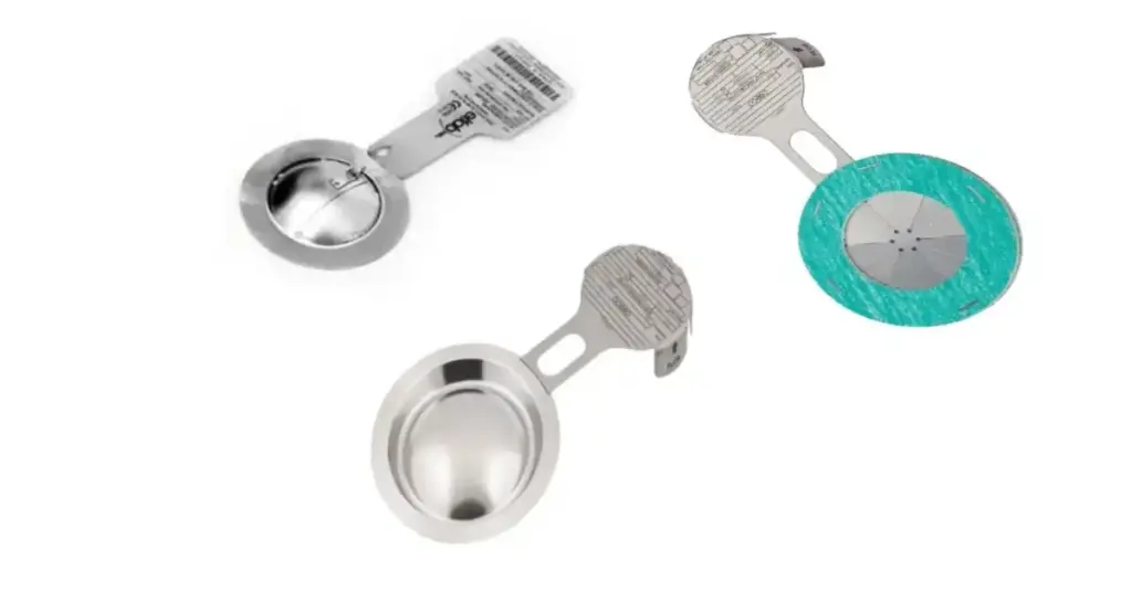
What is a Rupture Disc? A Full Guide (How They Work, Characteristics, & Uses) In the high-stakes world of industrial processing, pressure is a constant threat. If a pipe gets blocked or a chemical reaction runs out of control, pressure can build up in seconds, turning a steel tank into a potential bomb. To prevent this, most plants rely on safety valves. But valves have moving parts. They can seize, leak, or react too slowly to a sudden spike. Enter the Rupture Disc (also known as a Bursting Disc). It is the “airbag” of the process world—a simple, non-reclosing device that sacrifices itself to save your equipment. Once it activates, it’s gone, but your plant is safe. ADYAA supplies and distributes Rupture Discs in Australia, providing critical safety devices to local mining, oil & gas, and manufacturing industries. In this full guide, we will break down exactly what a Rupture Disc is, how it works, and why it might be the most important piece of metal in your facility. 1. What is a Rupture Disc? A Rupture Disc is a pressure relief device that consists of a thin, calibrated metal foil (the membrane) held between two metal holders. It is designed to be the “weakest link” in your pressure vessel. When the pressure inside the system hits a specific limit (the Burst Pressure), the disc physically tears open, allowing fluid or gas to escape instantly and relieving the pressure. Unlike a safety valve, which opens and then closes again, a Rupture Disc is a non-reclosing device. Once it bursts, it must be replaced. 2. How Do They Work? The mechanism is pure physics. Normal Operation: The disc acts as a solid seal, keeping the process fluid inside the pipe. Pressure Rise: As pressure builds, the metal foil begins to stress. Burst Point: When the pressure differential across the disc exceeds its tensile strength (the set pressure), the metal fails. Relief: The disc opens fully (in milliseconds), creating an unrestricted path for the gas or liquid to vent out safely. 3. Key Characteristics & Types Not all discs are the same. Engineers select a Rupture Disc based on specific characteristics: A. Forward Acting (Tension Loaded) How it works: The pressure pushes against the concave (hollow) side of the dome. The metal stretches until it snaps, like blowing up a balloon until it pops. Best for: Lower operating pressures and static loads. B. Reverse Acting (Compression Loaded) How it works: The pressure pushes against the convex (bulging) side of the dome. When the pressure hits the limit, the dome “snaps” through (inverts) and is sliced open by a knife blade or scored lines on the metal. Best for: High operating pressures (up to 95% of burst pressure) and cycling conditions. C. Materials Discs are made from exotic materials to resist corrosion and ensure precision. Common materials include Stainless Steel (316L), Inconel, Monel, Nickel, and Graphite. 4. Applications & Use Cases Where do you actually install a Rupture Disc? 1. As a Primary Relief Device Used on vessels where a valve is too expensive, too slow, or simply unnecessary. Example: A chemical reactor where a runaway reaction creates a pressure spike faster than a valve can open. 2. Upstream of a Safety Valve (The “Bodyguard”) This is the most common industrial use. The disc is installed before a Safety Relief Valve. Why? It seals the expensive valve off from corrosive chemicals or sticky fluids that would gum up the valve internals. If the pressure spikes, the disc bursts, and then the valve opens. 3. Downstream of a Safety Valve Installed on the outlet to prevent corrosive vapors from the header system entering the valve from the back. 5. Advantages of Using a Rupture Disc Why choose a disc over a valve? Zero Leakage: It is a solid metal seal. Unlike valves, which can “simmer” or leak slightly, a disc is bubble-tight. Essential for toxic or expensive gases. Instant Response: There is no spring to compress or piston to move. It opens in milliseconds. Cost-Effective: A disc is significantly cheaper than a high-performance safety valve. Low Maintenance: It has no moving parts. No lubrication or adjustment is needed. 6. FAQ: People Also Ask Here are the answers to the most common questions about Rupture Discs. What happens if a disc ruptures? When a disc ruptures, it creates an open path for the process fluid to escape. The system pressure drops rapidly. However, because the seal is broken, the process fluid will continue to vent until the system is shut down or isolated. You must stop production to replace the disc. What is the life of a rupture disc? A Rupture Disc does not last forever. Fatigue from pressure cycling (going up and down) eventually weakens the metal. Recommendation: Most manufacturers recommend replacing discs once a year during preventative maintenance, even if they haven’t burst. Harsh conditions: In corrosive or high-cycling environments, they may need replacement every 6 months. Where is the rupture disc located? They are typically located directly on the pressure vessel nozzle or in the piping immediately before a Safety Relief Valve. They are mounted inside a specialized Safety Head (holder) that is bolted between two pipe flanges. What does a rupture disc look like? It looks like a round, slightly domed metal plate, usually with a metal tag handle sticking out. The tag contains vital info like the Burst Pressure, Temperature Rating, and Flow Direction arrow. Note: Never paint over the disc or the tag! Conclusion: A Small Device with a Big Job A Rupture Disc is often the last line of defense between safe operation and a major incident. It is simple, reliable, and absolutely critical. Whether you need to protect a storage tank from vacuum collapse or shield a safety valve from corrosion, choosing the right disc requires expert sizing. ADYAA supplies and distributes Rupture Discs in Australia, offering high-precision safety heads tailored to your plant’s unique hazards. Ready to secure your pressure systems? Explore ADYAA Rupture Discs
Tank Protection Valve Full Guide: Types, Benefits & Selection
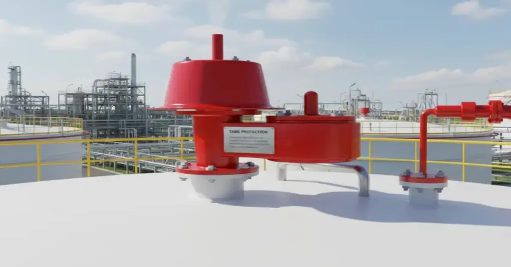
Tank Protection Valve Full Guide: Types, Benefits & Selection A bulk storage tank is not just a static metal box; it is a breathing lung. As temperatures rise during the day, the liquid inside expands and vapors build up (Exhalation). At night, or when pumping liquid out, the tank cools and creates a vacuum (Inhalation). If you block this breathing process, the physics are unforgiving: the tank will either rupture from overpressure or crumple inward like a crushed soda can. To prevent this catastrophe, engineers rely on a critical device: the Tank Protection Valve. ADYAA supplies, we specialize in low-pressure safety systems that keep Australian storage terminals compliant and safe. In this Tank Protection Valve full guide, we will explore what these valves are, the different types available, and how to assess which one is right for your facility. 1. What is a Tank Protection Valve? A Tank Protection Valve (often called a Breather Valve or PVRV) is a self-acting safety device mounted on the roof of a storage tank. Its primary job is to control the pressure inside the tank. Overpressure Relief: When internal pressure exceeds a set limit (e.g., due to filling or heat), the valve lifts to vent gas out. Vacuum Relief: When internal pressure drops (e.g., due to draining or cooling), the valve opens to let air (or inert gas) in. Unlike standard safety valves which handle high pressure (bars), a Tank Protection Valve operates at very low pressures (millibars or inches of water column). 2. Types of Tank Protection Valves Not all tanks breathe the same way. Depending on your stored product (flammable, toxic, or harmless), you need specific equipment. A. Pressure / Vacuum Relief Valve (PVRV) This is the standard “Breather Valve.” It handles both overpressure and vacuum in a single unit. Use Case: Standard diesel, water, or oil storage tanks. It reduces vapor loss by keeping the tank sealed until necessary. B. Emergency Relief Vent (ERV) A PVRV handles daily breathing, but what if there is a fire surrounding the tank? The liquid boils rapidly, creating massive vapor volume that a small PVRV cannot handle. Function: An ERV is a heavy weighted hatch that flips open only during emergency overpressure to prevent the tank from exploding. C. Tank Blanketing Valve (Pad Valve) For flammable or sensitive liquids (like methanol or food oils), you don’t want oxygen entering the tank. Function: Instead of letting in air, this valve injects an inert gas (usually Nitrogen) to fill the empty space. This prevents oxidation and eliminates the risk of an internal explosion. 3. Key Benefits (The Value of Protection) Why invest in high-quality ADYAA breathing valves instead of a simple open vent? 1. Safety & Structural Integrity The most obvious benefit is preventing tank failure. A collapsed tank can cost hundreds of thousands of dollars to replace, not to mention the environmental cleanup costs. 2. Reduced Vapor Loss (Cost Savings) An open vent lets expensive products evaporate into the sky 24/7. A Tank Protection Valve keeps the tank sealed 95% of the time, only opening when absolutely necessary. This retains the product and saves money. 3. Environmental Compliance Strict EPA and Australian environmental laws limit the amount of Volatile Organic Compounds (VOCs) you can release. A tight-sealing valve significantly reduces your emissions footprint. 4. How is a Tank Protection Valve Assessed? (Selection Criteria) Selecting the right valve is not guesswork; it is a calculation based on API 2000 standards. When assessing a valve for your tank, engineers look at three main factors: A. Set Pressure & Vacuum You must know the Maximum Allowable Working Pressure (MAWP) of your tank. The Rule: The Tank Protection Valve must open below the tank’s failure point but above the normal operating pressure to avoid constant venting. B. Flow Capacity (Breathing Requirement) How fast are you filling or emptying the tank? If you pump liquid out at 1,000 Liters/minute, the valve must be able to suck in air at that same rate (plus thermal contraction). If the valve is too small, you pull a vacuum and buckle the tank. C. Material Compatibility Is the fluid corrosive? For water, Aluminum is fine. For acids or sour gas, you need 316 Stainless Steel or Hastelloy internals to prevent the pallet from sticking. 5. Why Choose ADYAA for Tank Protection? In the harsh Australian sun, seals dry out and pallets get stuck. You need equipment built for our climate. ADYAA supplies and distributes robust Tank Protection Valves designed for longevity and precision. Whether you need a simple breather for a water tank or a complex nitrogen blanketing system for a chemical reactor, we have the stock and the engineering expertise to support you. Don’t leave your storage assets exposed. Explore ADYAA Tank Protection Valves View Emergency Vents & Flame Arrestors Contact us. How Industrial Automation Sensors Improve Automation & Efficiency in Manufacturing How Industrial Automation Sensors Improve Automation & Efficiency in Manufacturing In modern manufacturing, efficiency, accuracy, and reliability are more important… Read More → How Vision & Imaging Sensors Transform Automated Inspection Systems How Vision & Imaging Sensors Transform Automated Inspection Systems Maintaining product quality while keeping up with high-speed production is crucial…. Read More → IoT and Automation in Industrial Operations: Boost Efficiency, Safety, and Reliability IoT and Automation in Industrial Operations: Boost Efficiency, Safety, and Reliability Discover how IoT and automation revolutionize industrial operations. Improve… Read More →
Safety Relief Valve vs Pressure Relief Valve: The Key Differences
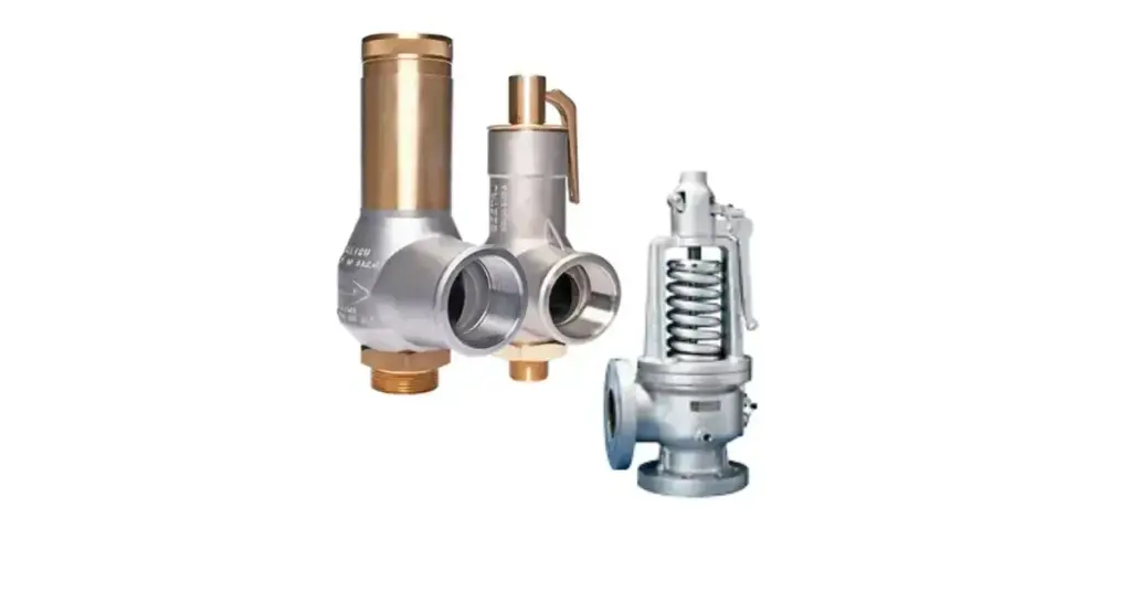
Safety Relief Valve vs Pressure Relief Valve: The Key Differences In the world of industrial process control, terms often get thrown around loosely. You’ll frequently hear engineers say “Relief Valve” when they mean “Safety Valve,” and vice versa. But if you are the one signing off on a purchase order—or worse, the one responsible for plant safety during an audit—you know that Safety Relief Valve vs Pressure Relief Valve isn’t just a semantic argument. It is a critical engineering distinction. Choosing the wrong device for your medium (Gas vs. Liquid) doesn’t just mean your system will be inefficient; it means it could be dangerous. A valve designed to “pop” open for steam might hammer itself to destruction if used on water. ADYAA supplies comprehensive pressure relief systems to industries worldwide. In this guide, we are clearing up the confusion so you can specify the right valve for your line with confidence. Safety Relief Valve and Pressure Relief Valve for Plant Engineers, Maintenance Managers, and Safety Officers. 1. What is a Safety Valve? (The “Pop” Action) A Safety Valve is a safety device designed to open rapidly and fully the moment the pressure hits the set limit. Think of a balloon popping—it doesn’t release air slowly; it releases it all at once. Primary Use: Compressible fluids (Steam, Air, Gas). Mechanism: It relies on the kinetic energy of the expanding gas to lift the valve disc instantly to 100% open. Why use it? Gases expand rapidly. If a boiler is over-pressurizing, you need to vent a massive volume of gas immediately to prevent an explosion. A slow-opening valve would be too dangerous in this scenario. 2. What is a Pressure Relief Valve? (The “Gradual” Action) A Pressure Relief Valve (PRV) is designed to open gradually, proportional to the increase in pressure. Think of turning on a kitchen tap—the more you turn it, the more water flows. If the pressure is 10% over the limit, the valve opens 10%. If the pressure drops, the valve slowly closes. Key Functions: Proportional Control: It modulates the opening to release only as much fluid as necessary to bring the pressure back down. Protection: It acts as a limit on the maximum pressure in a hydraulic or liquid circuit. Primary Benefits: Prevents Water Hammer: Because it opens and closes gradually, it avoids the sudden shockwaves (hydraulic shock) that destroy pipes and pumps. System Stability: It maintains a steady pressure in the line without causing the massive pressure drops that a Safety Valve would cause. Liquid Compatibility: Specifically engineered for Non-Compressible fluids like Water, Oil, and Hydraulic Fluid. 3. Safety Relief Valve vs Pressure Relief Valve: The Comparison To decide which one you need, you simply have to look at how the valve reacts to pressure. The Core Difference: “Pop” vs. “Open” Safety Valve: Snaps open to 100% lift instantly. (Digital: On/Off). Relief Valve: Opens slowly as pressure builds. (Analog: Proportional). Comparison Table: PSV vs. PRV Save this cheat sheet for your next planning meeting. Feature Safety Valve Pressure Relief Valve Action Rapid “Pop” Opening (Snap Action) Gradual Opening (Modulating) Primary Medium Gas, Steam, Air (Compressible) Water, Oil, Chemicals (Non-Compressible) Goal Prevent Catastrophic Failure (Explosion) Control Pressure / Protect Equipment Reset Pressure Closes well below set pressure (Blowdown) Closes near set pressure Common Use Boilers, Steam Drums, Air Receivers Hydraulic Lines, Pump Discharge, Lube Systems 4. What is a “Safety Relief Valve”? (The Hybrid) Here is where it gets tricky. You will often see the term Safety Relief Valve (SRV). An SRV is a versatile specialized valve that can function as either a Safety Valve or a Relief Valve, depending on the application. On Gas/Steam: It “pops” open. On Liquid: It opens in proportion to the pressure rise. ADYAA Insight: Many modern plants standardize on Safety Relief Valves to reduce inventory complexity, but you must ensure the trim and seal materials are compatible with your specific process fluid. 5. Beyond the Valve: ADYAA Protection Systems Sometimes, a valve isn’t the right solution—or it isn’t enough on its own. At ADYAA, we often recommend a layered approach to safety. Rupture Discs: A non-reclosing metal foil that bursts at a set pressure. Used as a fail-safe backup or for viscous fluids that would gum up a valve spring. Tank Protection (Vents): Breather valves that manage both venting and vacuum to prevent storage tanks from imploding during draining. Flame Arrestors: Essential for fuel lines to stop external fires from traveling back down the pipe into the tank. 6. How to Select the Right ADYAA Valve When you contact ADYAA for a relief system, we will guide you through three main questions: What is the State of Matter? Gas/Steam $rightarrow$ You likely need a Safety Valve. Liquid $rightarrow$ You likely need a Pressure Relief Valve. What is the Set Pressure? We need to know the exact point you want the valve to lift. What is the “Back Pressure”? Is the valve venting to the atmosphere (open air) or into a closed pipe system? Back pressure in pipes can affect when the valve opens. Conclusion: Don’t Guess with Safety The difference between Safety Relief Valve vs Pressure Relief Valve is the difference between a controlled release and a catastrophic pipe failure. Whether you need a Rupture Disc for a chemical reactor or a standard Pressure Relief Valve for a hydraulic pump, getting the specs right is non-negotiable. ADYAA offers pressure relief systems designed for reliable performance in harsh industrial environments. Need to secure your pressure vessels? Explore ADYAA Safety Valves & Rupture Discs View Tank Protection & Flame Arrestors Contact our Engineering Team for a Sizing Consultation. How Industrial Automation Sensors Improve Automation & Efficiency in Manufacturing How Industrial Automation Sensors Improve Automation & Efficiency in Manufacturing In modern manufacturing, efficiency, accuracy, and reliability are more important… Read More → How Vision & Imaging Sensors Transform Automated Inspection Systems How Vision & Imaging Sensors Transform Automated Inspection Systems Maintaining product quality while keeping up with high-speed production is crucial…. Read More →