Why Pressure Sensor Calibration Is Critical for Plant Safety?
Why Pressure Sensor Calibration Is Critical for Plant Safety? Imagine driving your car on the highway. You look down at the speedometer, and it says you are doing 100 km/h. But in reality, due to a mechanical fault, you are doing 120 km/h. You feel safe, but you are actually in the danger zone, risking a fine or an accident. This same scenario plays out every day in industrial plants, but the stakes are much higher. A pressure transmitter is the speedometer of your process. If it lies to you, your control system makes decisions based on bad data. This is why Pressure Sensor Calibration is not just a “nice-to-have” maintenance task—it is a non-negotiable requirement for operational safety. ADYAA looks at the results of neglected instruments all too often. In this guide, we break down exactly why keeping your pressure instruments accurate is the backbone of a safe facility. The Silent Enemy: What Is Sensor “Drift”? Many facility managers assume that once a sensor is installed, it stays accurate forever. Unfortunately, this is not true. All sensors suffer from “drift”—a gradual degradation of accuracy over time. This happens due to: Mechanical Fatigue: The diaphragm inside a pressure sensor flexes thousands of times a day. Like a paperclip bent back and forth, it eventually loses elasticity. Temperature Cycling: Extreme heat and cold cause expansion and contraction, shifting the sensor’s zero point. Over-Pressure Events: A sudden spike (water hammer) can permanently deform the sensing element. Regular Pressure Sensor Calibration is the only way to detect this drift and reset the instrument to the “truth.” 1. Preventing Catastrophic Failure (The Sealing Connection) The most immediate risk of an uncalibrated sensor is safety. If your pressure transmitter reads 10% lower than the actual pressure, your pumps might keep pushing fluid into a tank that is already full, or a pipe that is already at its limit. As we discussed in our guide on Industrial Sealing, gaskets and O-rings have specific pressure ratings. If the system pressure exceeds these limits because a sensor failed to trigger a shut-off valve, you risk a blowout. Pressure Sensor Calibration ensures that your system pressure never unknowingly exceeds the design limits of your RTJ Gaskets or flanges, preventing leaks, fires, and explosions. 2. Ensuring Product Quality and Consistency In industries like Food & Beverage or Chemical Processing, pressure dictates quality. Filtration: If differential pressure sensors across a filter are inaccurate, you might push contaminants through the filter media. Reaction Vessels: Chemical reactions often require precise pressures to occur. A deviation can ruin an entire batch. By prioritizing Pressure Sensor Calibration, you ensure that your “recipe” is followed exactly, every single time. This reduces scrap and guarantees that the product leaving your factory meets customer specifications. 3. Compliance and Audits (ISO & API) For most Australian industries, calibration is a legal or contractual obligation. ISO 9001: Requires that measuring equipment be verified at specified intervals. Safety Standards: Regulators require proof that safety-critical loops (like Safety Relief Valve triggers) are functional. During an audit, a missing calibration sticker or an expired certificate is a major non-conformance. Routine Pressure Sensor Calibration provides the traceable paper trail you need to pass audits with flying colours. 4. Energy Efficiency An uncalibrated sensor can quietly steal money from your energy budget. Consider a compressed air system. If the pressure switch reads lower than the actual pressure, the compressor will work harder and run longer than necessary to reach the “set point.” You end up paying for electricity to generate pressure you do not actually need. Accurate sensors ensure your automation systems run efficiently, aligning with the principles outlined in our Industrial Automation Sensors efficiency guide. How Often Should You Calibrate? There is no “one size fits all” answer, but here are the general rules of thumb: Critical Safety Transmitters: Every 6 to 12 months. Custody Transfer (Billing) Meters: Every 3 to 6 months. General Process Indication: Every 12 to 24 months. However, if a sensor experiences a shock, vibration, or extreme temperature event, it should be checked immediately. The ADYAA Difference ADYAA does not just put a sticker on the gauge. Whether performed in our NATA-traceable lab or at your site, our Pressure Sensor Calibration service involves a full health check of the unit. We adjust, clean, and verify the instrument across its full range to ensure linearity and hysteresis are within tolerance. Don’t let a $500 sensor put your million-dollar plant at risk. Is your calibration schedule up to date? Book Your Pressure Sensor Calibration Service. Contact us for a free audit of your instrument needs. When to Replace Rupture Discs in Pressure Equipment: A Maintenance Guide When to Replace Rupture Discs in Pressure Equipment: A Maintenance Guide In the world of pressure safety, the rupture disc… Read More → Flange Sealing Solutions for High-Pressure Pipes: Zero Leakage Strategies Flange Sealing Solutions for High-Pressure Pipes: Zero Leakage Strategies In high-pressure industrial environments, the weakest link is rarely the pipe… Read More → How to Select Pressure Relief Valves for Industrial Plants How to Select Pressure Relief Valves for Industrial Plants If a pump fails, production stops. If a control valve fails,… Read More →
Rupture Discs vs Relief Valves Explained: Making the Right Choice
Rupture Discs vs Relief Valves Explained: Making the Right Choice When designing a pressure vessel, you have a critical obligation to ensure it does not fail under pressure. But when it comes to selecting the device that provides that protection, engineers often face a classic debate: Rupture Discs vs Relief Valves. Is it better to have a device that recloses to save your product? Or one that bursts open instantly to guarantee maximum flow? The answer, as with most complex engineering challenges, is rarely black and white. It depends entirely on your process fluid, your risk tolerance, and your maintenance capabilities. We manage the lifecycle of both technologies. We know that choosing the wrong device can lead to expensive product loss or, worse, a safety system that reacts too slowly. In this guide, we break down the Rupture Discs vs Relief Valves comparison to help you select the right strategy for your plant. The Safety Relief Valve (SRV): The Reclosing Workhorse A Safety Relief Valve (SRV) is a mechanical device designed for continuity. A spring holds a disc down against a seat. When the system pressure exceeds the spring force, the valve lifts, releases the excess pressure, and then closes again once safe conditions are restored. The Pros: Reclosing Capability: This is the primary advantage. You don’t lose the entire contents of your tank during a minor pressure spike. Adjustability: The set pressure can often be fine-tuned by a technician to suit changing process needs. Serviceability: These are assets you can maintain. We can test, machine, and repair these valves to extend their operational life significantly. The Cons: Leakage Risk: Because it relies on a mechanical seat, there is always a risk of small “simmering” leaks, especially as operating pressure nears the set point. Mechanical Complexity: With moving parts, they are susceptible to sticking if fouled by product buildup, requiring regular testing. The Rupture Disc: The Instant “Circuit Breaker” A Rupture Disc (or Bursting Disc) is a thin metal membrane engineered to fail at a precise pressure. Think of it as the “fuse” of your pressure system. Once it bursts, it cannot be reset; the process is open to the atmosphere (or flare system) until the disc is physically replaced. The Pros: Hermetic Seal: There is zero leakage. This makes them ideal for toxic, expensive, or hazardous gases where fugitive emissions are unacceptable. Instant Full Bore: The disc opens completely in milliseconds, providing a massive escape path instantly. This is critical for fast-rising pressure events like runaway chemical reactions. Lower Upfront Cost: A disc is generally less expensive to purchase than a high-specification valve. The Cons: One-Shot Device: Once it activates, your plant is down until a technician installs a new one. Non-Adjustable: You buy it for a specific burst pressure. If your process changes, you must buy new discs. The Showdown: Rupture Discs vs Relief Valves To decide between the two, you need to weigh your priorities. Here is a quick comparison of how they stack up in the field: Feature Safety Relief Valve (SRV) Rupture Disc Action Recloses (Saves Product) Non-reclosing (Sacrificial) Sealing Potential for simmering Zero leakage (Hermetic) Maintenance Requires testing & repair Requires replacement after use Response Time Fast Instant (Milliseconds) Best Application Variable/Minor Upset Conditions Explosions/Runaway Reactions The Ultimate Solution: The Combination Strategy In many critical applications, the best answer to Rupture Discs vs Relief Valves is actually “both.” By installing a Rupture Disc upstream of a Relief Valve, you achieve a superior level of protection: Corrosion Protection: The disc acts as a shield, preventing corrosive process fluids from touching the expensive valve internals during normal operation. Zero Leakage: The disc provides a tight seal, ensuring valuable gas doesn’t leak through the valve seat. Reclosing Capability: If an overpressure event occurs, the disc bursts, the valve opens to relieve pressure, and then the valve closes. You still have to replace the disc, but you do not lose the whole tank inventory. Note: This setup requires careful monitoring of the space between the disc and the valve to ensure no back-pressure builds up, which would change the burst pressure. Managing Your Lifecycle with Data Whether you choose discs, valves, or a combination, they all require intelligent management. At ADYAA, we move beyond rigid, calendar-based maintenance schedules. We utilise Risk-Based Inspection (RBI) methodologies to calculate the unique risk profile for every relief device in your facility. This data-driven approach allows us to tell you exactly which valves need immediate repair and which can safely run longer—optimising your budget without compromising safety. Confused about your safety strategy? Don’t guess with overpressure protection. Let our engineers calculate the right sizing and selection for your specific risk profile. Contact ADYAA for Pressure Relief System Management Call us for support on all major valve brands. When to Replace Rupture Discs in Pressure Equipment: A Maintenance Guide When to Replace Rupture Discs in Pressure Equipment: A Maintenance Guide In the world of pressure safety, the rupture disc… Read More → Flange Sealing Solutions for High-Pressure Pipes: Zero Leakage Strategies Flange Sealing Solutions for High-Pressure Pipes: Zero Leakage Strategies In high-pressure industrial environments, the weakest link is rarely the pipe… Read More → How to Select Pressure Relief Valves for Industrial Plants How to Select Pressure Relief Valves for Industrial Plants If a pump fails, production stops. If a control valve fails,… Read More →
Why Dew Point Sensors Are Critical in Industrial Air and Gas Systems
Why Dew Point Sensors Are Critical in Industrial Air and Gas Systems In the world of industrial automation and pneumatic power, water is the enemy. It is invisible in its vapor form, but once it condenses into liquid, it becomes a destructive force capable of rusting pipes, ruining sensitive tools, and contaminating end products. Many facilities focus heavily on pressure and flow, often treating moisture monitoring as an afterthought. However, seasoned engineers know that Dew Point Sensors Are Critical in Industrial Air and Gas Systems for maintaining operational integrity and efficiency. ADYAA specializes in the instrumentation that keeps your processes safe. In this deep dive, we explore the science of dew point and why ignoring it is a risk you cannot afford to take. What Is Dew Point and Why Does It Matter? “Dew Point” is the temperature at which air becomes saturated with water vapor. If the air cools below this temperature, the airborne vapor turns into liquid water (condensation). In industrial contexts, we specifically talk about Pressure Dew Point (PDP). Because compressing air concentrates the water vapor, the dew point rises significantly under pressure. Air that seems “dry” at ambient pressure will immediately drop gallons of water once compressed if not properly treated. Understanding this thermodynamic reality is the first step in realizing why Dew Point Sensors Are Critical in Industrial Air and Gas Systems. Without them, you are flying blind regarding the moisture content in your lines. The 4 Major Risks of Unmonitored Moisture If you are not actively monitoring dew point, you are likely experiencing one of these four expensive problems: 1. Corrosion and Equipment Failure Water in pneumatic lines washes away the lubricants needed for cylinders and valves. Over time, this causes: Rust and Scale: This debris travels through the pipes, clogging orifices and damaging expensive actuators. Frozen Lines: In outdoor installations or cold climates, condensed water freezes, blocking airflow and potentially bursting pipes. 2. Product Contamination (Food & Pharma) In regulated industries, air often touches the product. Imagine a pharmaceutical powder clumping because the conveying air was moist, or bacteria growing in a food package because the “clean” air contained water droplets. In these high-stakes environments, Dew Point Sensors Are Critical in Industrial Air and Gas Systems to ensure compliance with strict hygiene standards like ISO 8573-1. 3. Compromised Analytical Instruments Many industrial analyzers and precision instruments require “Zero Air” or ultra-dry gas to function. Moisture can drift sensor readings or permanently damage the sensitive optics and detection elements inside these devices. 4. Energy Waste in Dryers Most facilities use Desiccant or Refrigerant dryers to remove moisture. Without a sensor, these dryers often run on a fixed timer—regenerating the desiccant beds every 10 minutes whether they need it or not. By using a dew point sensor to control the dryer (Dew Point Demand Switching), you only regenerate when the sensor detects moisture. This can save thousands of dollars in energy costs annually. Choosing the Right Sensor Technology Not all sensors are created equal. Selecting the right one depends on how dry your air needs to be. Polymer Sensors: Excellent for standard compressed air applications (Refrigerant dryers) where the dew point is around +3°C. They are robust, fast-responding, and cost-effective. Aluminum Oxide / Metal Oxide Sensors: The standard for “critical dry” air (Desiccant dryers) where dew points can reach -40°C or even -100°C. These are highly sensitive and essential for semiconductor or medical gas applications. Installation Best Practices To ensure your data is accurate, proper installation is key. Install at the Point of Use: While checking the compressor room is important, measuring at the end of the line (near the critical machine) ensures that no moisture has re-entered the system through leaks. Use a Sampling Cell: Placing a sensor directly in a high-velocity air stream can damage it or cause errors. A sampling cell controls the flow across the sensor for a stable reading. Regular Calibration: Like all precision instruments, dew point sensors drift over time. Regular calibration (as offered by ADYAA) ensures you aren’t relying on false “dry” readings. Conclusion: A Small Sensor for Big Peace of Mind Moisture damage is cumulative. By the time you see water dripping out of a pneumatic tool, the damage to the internal seals is already done. Implementing continuous monitoring is the only proactive solution. It allows you to catch dryer failures instantly, automate energy savings, and guarantee product quality. This is why Dew Point Sensors Are Critical in Industrial Air and Gas Systems—they are the final check that validates your entire air treatment process. ADYAA supplies a range of high-precision dew point transmitters and portable meters designed for the harsh conditions of Australian industry. Stop guessing about your air quality. View ADYAA’s Range of Dew Point Sensors Contact our team to discuss your compressed air requirements. Why Dew Point Sensors Are Critical in Industrial Air and Gas Systems Why Dew Point Sensors Are Critical in Industrial Air and Gas Systems In the world of industrial automation and pneumatic… Read More → Understanding Thermowells and Their Role in Process Instrumentation Understanding Thermowells and Their Role in Process Instrumentation In the vast ecosystem of process control, temperature is often the most… Read More → 5 Signs Your Equipment Needs Calibration Now 5 Signs Your Equipment Needs Calibration Now In a perfect world, you would calibrate your instruments exactly according to the… Read More →
Understanding Thermowells and Their Role in Process Instrumentation
Understanding Thermowells and Their Role in Process Instrumentation In the vast ecosystem of process control, temperature is often the most critical variable. Whether you are refining crude oil, pasteurizing milk, or managing chemical reactions, accurate temperature data is non-negotiable. However, the sensors that measure this temperature—Resistance Temperature Detectors (RTDs) and Thermocouples—are often delicate devices. Shutterstock They contain fine wires and sensitive elements that would be destroyed instantly if exposed directly to high-velocity steam, corrosive acids, or abrasive slurries. Enter the Thermowell. Often overlooked as a simple metal fitting, the thermowell is actually a critical safety barrier. ADYAA, knows that selecting the wrong thermowell doesn’t just mean a broken sensor; it can lead to catastrophic vessel failure. In this guide, we break down everything you need to know about thermowells and their role in process instrumentation. What Is a Thermowell? A Thermowell is a cylindrical pressure-tight fitting that protects temperature sensors from the process media. Think of it as “armor” for your sensor. It is installed directly into the pipe or vessel, and the temperature sensor (the probe) is inserted into the open end of the thermowell. The heat transfers from the process fluid, through the thermowell wall, and into the sensor. The Three Primary Functions Protection: It isolates the fragile sensor from pressure, high velocity, and corrosion. Serviceability: This is arguably its most important role for operations. A thermowell allows you to remove and replace a faulty sensor without shutting down the process or draining the tank. Containment: It acts as a part of the process boundary. If the sensor is removed, the thermowell keeps the liquid or gas inside the pipe. Anatomy of a Thermowell: Stem Profiles Not all thermowells are simple tubes. The shape of the “stem” (the part immersed in the fluid) dictates how the well handles pressure and how fast it responds to temperature changes. 1. Straight Stem The same diameter along the entire immersion length. Pros: Strong and easy to manufacture. Cons: Slower response time due to more metal mass at the tip; susceptible to flow-induced vibration. 2. Stepped Stem The diameter is reduced (stepped down) at the tip where the sensor sits. Pros: Faster response time (less metal at the tip) and good strength. Cons: Slightly lower pressure rating than tapered. Verdict: The most common standard for general industry. 3. Tapered Stem The diameter gradually decreases from the root to the tip. Pros: The strongest design. It offers the best resistance to vibration and high-velocity flow. Cons: More expensive to machine. Verdict: Essential for high-velocity steam lines and heavy-duty petrochemical applications. Connection Types: How It Fits Your Process Threaded: Screws directly into the pipe. Low cost and easy to install, but not recommended for high pressure or flammable/hazardous materials due to the risk of leakage at the threads. Flanged: The thermowell is welded to a flange, which is bolted to a mating flange on the pipe. This is the standard for Oil & Gas and Chemical industries as it provides a secure, high-pressure seal. Socket Weld / Weld-In: Welded directly into the pipe wall. This is a permanent solution used for extremely high pressure (like steam generation) where no leakage path is permitted. The Hidden Danger: Wake Frequency and Vibration This is the most technical and critical part of thermowell selection. When fluid flows past a thermowell, it doesn’t just flow smoothly; it creates vortices (swirls) that shed from alternating sides of the stem. This is known as the Von Karman Vortex Street. These shedding vortices create oscillating forces that make the thermowell vibrate. The Risk: If the frequency of these vibrations matches the Natural Frequency of the thermowell (its resonant “sweet spot”), the thermowell will vibrate violently and snap off inside the pipe. The Result: The sensor is lost, and worse, you now have an open hole in your pipe spewing process fluid. The Solution: Always perform a Wake Frequency Calculation (per ASME PTC 19.3 TW-2016 standards) before installing thermowells in high-velocity lines. This calculation ensures the stem is thick enough and short enough to withstand the flow. Selecting the Right Material Since the thermowell is in direct contact with the media, material selection is vital to prevent corrosion. Stainless Steel (304/316): The industry standard for water, air, and mild chemicals. Monel / Hastelloy: Required for seawater or highly corrosive acids (Hydrochloric/Sulfuric). Inconel / Ceramic: Used for extremely high temperatures (furnaces and kilns) where steel would melt or oxidize. Conclusion: Small Component, Big Impact A thermowell might look like a simple piece of metal, but it is a highly engineered component that bridges the gap between delicate electronics and brutal industrial forces. Ignoring the details—like immersion length, material compatibility, or wake frequency—can lead to poor measurement accuracy or dangerous mechanical failures. ADYAA specializes in understanding that instrumentation isn’t just about reading a number on a screen; it’s about the safety and efficiency of your entire plant. Need help sizing the right thermowell for your application? Contact ADYAA’s Instrumentation Team Let us handle your Wake Frequency Calculations and material selection today. Why Dew Point Sensors Are Critical in Industrial Air and Gas Systems Why Dew Point Sensors Are Critical in Industrial Air and Gas Systems In the world of industrial automation and pneumatic… Read More → Understanding Thermowells and Their Role in Process Instrumentation Understanding Thermowells and Their Role in Process Instrumentation In the vast ecosystem of process control, temperature is often the most… Read More → 5 Signs Your Equipment Needs Calibration Now 5 Signs Your Equipment Needs Calibration Now In a perfect world, you would calibrate your instruments exactly according to the… Read More →
5 Signs Your Equipment Needs Calibration Now
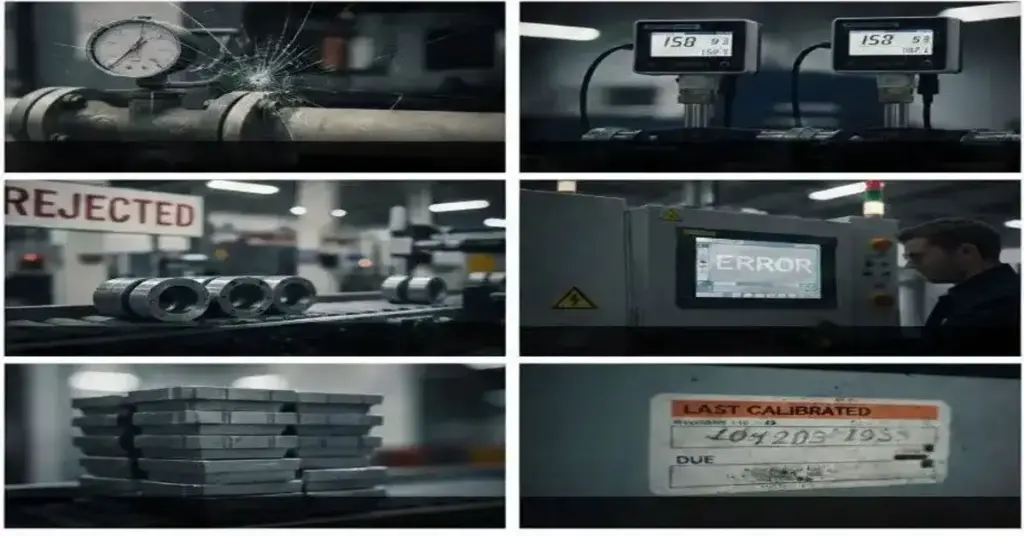
5 Signs Your Equipment Needs Calibration Now In a perfect world, you would calibrate your instruments exactly according to the manufacturer’s schedule—every 6 or 12 months, like clockwork. But in the real world of busy production schedules and tight budgets, maintenance sometimes slips. The problem is, your sensors don’t wait for a schedule to start failing. Drift happens. Wear and tear happen. Accidents happen. Relying on an outdated sticker to tell you if your equipment needs calibration is a risky strategy. Often, your machinery will tell you it’s struggling long before the due date arrives—you just have to know what to listen for. We help industries across Australia stay accurate. Here are the 5 red flags that indicate your equipment needs calibration immediately. 1. Your Product Quality Is Inconsistent The first victim of poor calibration is usually the product itself. The Symptom: You are running the same “recipe” or settings as always, but the results are changing. Maybe the chemical mix is slightly off, the coating thickness varies (a critical issue for our Elcometer users), or the fill levels in bottles are erratic. The Cause: If a flow meter or temperature sensor drifts, the machine thinks it is doing the right thing, but the reality doesn’t match the data. The Fix: If your output quality wavers, don’t blame the raw materials first. Check if your equipment needs calibration. 2. Readings Don’t Match “Common Sense” Experienced operators know their machines by heart. They know that when Pump A is running at 50Hz, the pressure usually sits at 5 Bar. The Symptom: A gauge shows zero pressure when a line is clearly pressurized, or a temperature sensor reads ambient room temp as 40°C. The Cause: Internal electronic components can fail, or diaphragms can become stiff. The Reality: Trust your operators. If they say “that gauge looks wrong,” it is a clear sign the equipment needs calibration or replacement. 3. Physical Damage or “Shock” Events Industrial environments are tough. Tools get dropped, forklifts bump into panels, and steam lines experience “water hammer.” The Symptom: A visible dent in a transmitter housing, a cracked gauge face, or a sensor that has been exposed to a sudden over-pressure spike. The Rule: Any instrument that suffers a significant physical shock is compromised. Even if it still “works,” the internal mechanism may be bent or shifted. The Fix: Don’t wait for the annual check. A shocked sensor is an unreliable sensor. 4. Energy Bills Are Spiking As we explored in our post on Industrial Automation Sensors, efficiency relies on accurate data. The Symptom: Your power consumption is creeping up, but production volume hasn’t increased. The Cause: If a temperature sensor reads lower than the actual temperature, a boiler or heater will burn extra fuel trying to reach a setpoint it has already exceeded. The Reality: In this case, the cost of the wasted energy is often higher than the cost of the service. This phantom cost is a major indicator that your equipment needs calibration. 5. You Have an Audit or Certification Coming Up This is the most common trigger, but often it’s left too late. The Symptom: An ISO 9001, API, or safety audit is scheduled for next month, and you realize your certificates expired three weeks ago. The Risk: An auditor finding an expired label on a critical control point is an immediate non-conformance. The Fix: Proactive planning. If an audit is looming, review every critical asset. If the date is close, assume the equipment needs calibration now to avoid the scramble. Don’t Guess—Verify. Ignoring these signs leads to scrap, safety hazards, and downtime. Whether you need a quick verification of a handheld device or a full loop check of a critical safety system, ADYAA has the solution. We offer both On-Site and Lab Calibration to suit your urgency. If you spot any of these 5 signs, do not wait for the breakdown. Think your sensors are drifting? Schedule a Calibration Check with ADYAA Call our support team for emergency service. Why Dew Point Sensors Are Critical in Industrial Air and Gas Systems Why Dew Point Sensors Are Critical in Industrial Air and Gas Systems In the world of industrial automation and pneumatic… Read More → Understanding Thermowells and Their Role in Process Instrumentation Understanding Thermowells and Their Role in Process Instrumentation In the vast ecosystem of process control, temperature is often the most… Read More → 5 Signs Your Equipment Needs Calibration Now 5 Signs Your Equipment Needs Calibration Now In a perfect world, you would calibrate your instruments exactly according to the… Read More →
Coating Thickness Inspection for Improved Process Reliability

Coating Thickness Inspection for Improved Process Reliability In industrial manufacturing, a layer of paint or coating is rarely just for decoration. It is a functional shield designed to protect expensive assets from corrosion, abrasion, and extreme temperatures. However, applying this shield is a delicate balancing act. Apply too little, and the protection fails prematurely. Apply too much, and you waste expensive material or cause issues like cracking and prolonged curing times. This is where Coating Thickness Inspection becomes the linchpin of process reliability. ADYAA, understands that reliable measurement is the difference between a product that lasts for decades and one that fails in months. In this guide, we explore the methods, standards, and strategic value of rigorous thickness testing. Why Coating Thickness Matters The thickness of a coating—often referred to as Dry Film Thickness (DFT)—is the most critical parameter in determining the lifespan of a protective system. Corrosion Prevention: Most industrial specifications (like ISO 12944) mandate a specific minimum thickness to ensure an adequate barrier against moisture and oxygen. Mechanical Fit: In precision engineering, an overly thick coating can interfere with the assembly of parts, causing production delays. Cost Control: “Over-coating” by just 10% across a year of production can cost a factory thousands of dollars in wasted paint. By implementing a strict Coating Thickness Inspection regime, you ensure that every part meets the “Goldilocks” standard—not too thick, not too thin, but just right. Methods of Inspection: How It Works Modern technology allows us to measure thickness without damaging the part. The method you choose depends heavily on the substrate (the material underneath the paint). 1. Magnetic Induction (Ferrous Substrates) This is the standard method for measuring non-magnetic coatings (paint, plastic, galvanizing) over magnetic substrates like steel or iron. How it works: The probe generates a magnetic field. The thickness of the coating changes the magnetic flux between the probe and the steel. The gauge converts this change into a thickness reading. 2. Eddy Current (Non-Ferrous Substrates) Used for measuring non-conductive coatings (anodizing, paint) on non-magnetic metals like aluminum, copper, or stainless steel. How it works: The probe creates high-frequency magnetic fields that induce eddy currents in the metal. The coating thickness affects the magnitude of these currents. 3. Ultrasonic Testing (Non-Metal Substrates) For measuring coatings on wood, concrete, or plastic, magnetic methods won’t work. Coating Thickness Inspection in these applications relies on ultrasonic pulses that reflect off the interface between the coating and the substrate. The Role of Calibration in Inspection You cannot trust your data if you cannot trust your gauge. Before every shift or critical batch, your Coating Thickness Inspection tools must be verified. This usually involves: Zeroing: Measuring on the uncoated, smooth substrate. Foil Calibration: Measuring a certified plastic shim of known thickness (e.g., 50 microns) placed over the substrate to ensure the gauge reads correctly. ADYAA supplies industry-leading gauges (such as Elcometer) and offer calibration services to ensure your NDT equipment remains traceable to national standards. How Inspection Improves Process Reliability Moving from “visual checking” to data-driven Coating Thickness Inspection transforms your operations in three ways: 1. Predictive Quality Control By integrating digital gauges that store data, you can track trends. If the average thickness is slowly creeping up over a week, you know a spray nozzle might be wearing out or a robot needs reprogramming before you start producing defective parts. 2. Compliance and Liability Protection In sectors like marine, aerospace, and oil & gas, proof of quality is mandatory. A digital inspection log provides a permanent record that the coating was applied according to spec. This is your insurance policy against warranty claims later. 3. Reducing Rework Catching a low-thickness area immediately after the curing oven allows for a quick touch-up. Catching it after the product has been shipped to the customer results in expensive field repairs and reputational damage. Reliable Coating Thickness Inspection keeps the problem inside the factory walls where it can be managed. Conclusion: Precision is Protection A coating is only as good as its application. Without accurate measurement, you are essentially guessing. Investing in high-quality inspection equipment and training your team on proper probe placement and calibration techniques is one of the highest-ROI activities a paint shop can undertake. It reduces waste, ensures compliance, and guarantees that your product can withstand the environment it was built for. Looking for reliable inspection tools? At ADYAA, we stock a wide range of NDT solutions, including the world-renowned Elcometer series. Explore Our Coating Thickness Gauges Contact our experts for advice on measuring complex substrates. Why Dew Point Sensors Are Critical in Industrial Air and Gas Systems Why Dew Point Sensors Are Critical in Industrial Air and Gas Systems In the world of industrial automation and pneumatic… Read More → Understanding Thermowells and Their Role in Process Instrumentation Understanding Thermowells and Their Role in Process Instrumentation In the vast ecosystem of process control, temperature is often the most… Read More → 5 Signs Your Equipment Needs Calibration Now 5 Signs Your Equipment Needs Calibration Now In a perfect world, you would calibrate your instruments exactly according to the… Read More →