Gems 3100/3200 Pressure Transmitters : Complete Guide
Gems 3100/3200 Pressure Transmitters: Complete Guide Accurate pressure monitoring is essential across industrial environments where process visibility, operational consistency and system performance matter. Selecting the right Pressure Transmitters can support reliable measurement, better integration and improved operational awareness. Whether you are evaluating a new installation or comparing an industrial pressure sensing solution, understanding application requirements is the first step. This guide explains what Gems 3100/3200 Pressure Transmitters are, how they work, selection considerations and practical applications across industrial environments. What Are Gems 3100/3200 Pressure Transmitters ? Gems 3100/3200 Pressure Transmitters are industrial devices designed to convert pressure into electrical output signals that can be interpreted by monitoring and control systems. Pressure Transmitters are widely used where continuous measurement and process visibility are important. Typical environments include: Industrial process applications Water and fluid systems Manufacturing equipment Hydraulic systems Automation environments OEM machinery Their purpose is simple: Measure pressure → convert into signal → support operational decisions. Why Pressure Transmitters Selection Matters Selecting a pressure transmitter involves more than choosing a pressure range. A well-selected industrial pressure Transmitters may support: Better process visibility Reliable pressure monitoring Easier system integration Improved operational awareness More consistent measurements Selecting equipment without considering the application may create: Unstable readings Increased maintenance Reduced measurement confidence Process inefficiencies For example: A production line operating under changing conditions may require a different pressure-sensing approach than a stable water application. 5 Factors to Consider Before Selecting Gems 3100/3200 Pressure Transmitters 1. Understand Operating Pressure Conditions Review: Normal operating pressure Peak conditions Temporary fluctuations Selecting the appropriate range supports measurement consistency. 2. Evaluate Process Compatibility Industrial processes vary. Consider: Water applications Process liquids Hydraulic fluids Industrial operating environments Review process requirements before selecting instrumentation. 3. Confirm Integration Requirements Pressure Transmitters should align with existing infrastructure. Typical environments include: PLC systems SCADA platforms Control systems Industrial monitoring systems System compatibility should always be evaluated before implementation. 4. Assess Environmental Conditions Environmental conditions influence performance. Evaluate: Temperature exposure Installation environment Moisture conditions Mechanical vibration Example: Outdoor industrial environments may have different requirements compared with controlled indoor installations. 5. Plan for Long-Term Operation Selection should support long-term use. Review: Accessibility Maintenance requirements Inspection schedules Operational continuity Reliable measurement starts with selecting solutions suitable for the application lifecycle. Common Applications of Gems 3100/3200 Pressure Transmitters Water Management Supports pressure visibility across fluid systems. Industrial Equipment Helps maintain process awareness. Hydraulic Systems Supports pressure monitoring under changing operating conditions. Manufacturing Applications Improves measurement visibility across production environments. Example: Selecting Pressure Transmitters for a Manufacturing Process Imagine a production environment operating multiple pressure zones. The engineering team reviews: ✔ Pressure requirements ✔ Environmental conditions ✔ Integration requirements ✔ Maintenance expectations Instead of selecting based only on specifications, they evaluate operating requirements first. This approach often supports better long-term outcomes. Best Practices for Pressure Monitoring To improve measurement performance: Select the correct operating range Confirm process compatibility Install according to requirements Perform periodic inspection Review operating conditions regularly Reliable monitoring combines appropriate selection with good operating practices. Frequently Asked Questions What are Gems 3100/3200 Pressure Transmitters used for? They are used to measure pressure and provide electrical signals for industrial monitoring and control applications. How do I select the correct pressure transducer? Review operating pressure, application requirements, environmental conditions and system compatibility. Can pressure transducers be used in water applications? Pressure Transmitters are commonly applied in industrial water environments depending on operating conditions. What industries commonly use pressure Transmitters ? Manufacturing, industrial automation, water systems and hydraulic applications commonly use pressure Transmitters . How often should pressure Transmitters be inspected? Inspection intervals vary depending on operating conditions and maintenance practices. Final Thoughts Selecting the correct pressure sensing solution requires more than reviewing technical specifications. Gems 3100/3200 Pressure Transmitters may be considered where pressure visibility, operational consistency, and industrial integration are important. Before final selection, evaluate operating requirements, installation conditions, and system compatibility to support long-term performance. Explore product details Electromagnetic Flow Meter for Distilled Water Applications – Copy Gems 3100/3200 Pressure Transmitters: Complete Guide Accurate pressure monitoring is essential across industrial environments where process visibility, operational consistency and… Read More → Dry Type Water Meters for Accurate Water Measurement Dry Type Water Meters: Why They Remain a Preferred Choice for Accurate Water Measurement Accurate water measurement is the foundation… Read More → Electromagnetic Flow Meter for Distilled Water Applications Electromagnetic Flow Meter for Distilled Water Applications Can an Electromagnetic Flow Meter Be Used for Distilled Water? Electromagnetic (Mag) flow… Read More →
Gems 3510 Pressure Transmitter: Complete Selection Guide
Gems 3510 Pressure Transmitter: Complete Selection Guide Accurate pressure monitoring plays an important role in industrial performance, process visibility and operational consistency. Selecting the right Pressure Transmitter can help improve measurement reliability, support system integration and contribute to more efficient process control. Whether you are evaluating an industrial pressure transmitter, upgrading an existing setup or comparing a pressure measurement solution, understanding selection criteria is essential. This guide explains how to evaluate the Gems 3510 Pressure Transmitter, where it may be applied and what factors to consider before making a decision. What Is a Gems 3510 Pressure Transmitter? The Gems 3510 Pressure Transmitter is designed to convert measured pressure into an output signal that can be used by industrial monitoring and control systems. Pressure transmitters are widely used to support operational monitoring and maintain process visibility across multiple industries. Typical application environments include: Industrial process systems Water and fluid applications Manufacturing environments Hydraulic systems Automation systems OEM equipment As a process pressure transmitter, its purpose is to convert process pressure into usable measurement data. Why Pressure Transmitter Selection Matters Choosing the right transmitter involves more than selecting a specification range. A properly selected pressure monitoring system may support: Improved process visibility More consistent measurements Better operational awareness Easier maintenance planning Reliable system integration Incorrect selection may lead to: Measurement instability Frequent maintenance intervention Reduced operational confidence Increased troubleshooting time For example: A water circulation process may require different pressure measurement conditions compared with a hydraulic production environment. Understanding the application should always come before selecting equipment. 5 Factors to Consider Before Selecting a Gems 3510 Pressure Transmitter 1. Understand the Operating Pressure Range Start by identifying: Normal operating pressure Maximum pressure Temporary surge conditions Selecting an unsuitable range may influence performance. Example: Operating within the normal measurement range instead of near limits may help maintain stable readings. 2. Evaluate Process Media Compatibility Industrial environments operate under different conditions. Consider: Water applications Industrial liquids Hydraulic fluids Process environments Questions to review: What media will be measured? Are environmental conditions stable? Is material compatibility suitable? Selection based on actual operating requirements generally supports better long-term outcomes. 3. Confirm System Integration Requirements Before installation, verify compatibility with: PLC systems SCADA environments Industrial control systems Monitoring platforms An industrial instrumentation setup performs best when devices communicate effectively across the system. 4. Review Environmental Conditions Pressure transmitters often operate in demanding industrial environments. Evaluate: Temperature exposure Moisture conditions Mechanical vibration Installation location Example: Outdoor applications may have different requirements compared with indoor control systems. 5. Consider Lifecycle and Maintenance Selection should support long-term operation. Review: Installation access Service requirements Inspection schedules Operational continuity Selecting a transmitter that supports ongoing maintenance can simplify long-term management. Common Applications of Gems 3510 Pressure Transmitter The Gems 3510 Pressure Transmitter may support several industrial environments. Water Management Systems Pressure monitoring may help improve operational visibility across fluid applications. Manufacturing Equipment Supports measurement awareness across industrial processes. Hydraulic Applications Provides pressure visibility under changing operating conditions. Industrial Automation Supports broader monitoring and operational control environments. Example: Selecting a Pressure Measurement Solution Imagine an industrial facility operating a closed-loop water process. The engineering team evaluates: ✔ Pressure range ✔ Environmental conditions ✔ Process requirements ✔ Integration compatibility Instead of selecting based only on specifications, they evaluate actual operating conditions. This approach may contribute to more reliable measurement outcomes. Best Practices for Better Pressure Measurement To improve long-term measurement performance: Select the correct operating range Verify process compatibility Follow installation recommendations Schedule periodic inspection Review operating conditions regularly The right pressure transmitter applications strategy combines correct selection with suitable operating practices. Frequently Asked Questions What is a Gems 3510 Pressure Transmitter used for? The Gems 3510 Pressure Transmitter is used to measure pressure and provide output signals for monitoring and industrial control environments. How do I choose the correct pressure transmitter? Evaluate operating pressure, environmental conditions, media compatibility and system integration requirements. Can pressure transmitters be used in water applications? Pressure transmitters are commonly applied in industrial water systems depending on operating requirements. What industries commonly use pressure transmitters? Pressure transmitters are frequently used in manufacturing, automation, hydraulic systems and water-related processes. How often should pressure transmitters be inspected? Inspection intervals depend on application conditions, maintenance schedules and operational requirements. Final Thoughts Selecting the right pressure transmitter requires understanding more than technical specifications. The Gems 3510 Pressure Transmitter may be considered where reliable pressure monitoring, process visibility and integration flexibility are important. Before implementation, review application requirements, environmental conditions and compatibility to support long-term operational performance. Explore product details Electromagnetic Flow Meter for Distilled Water Applications – Copy Gems 3100/3200 Pressure Transmitters: Complete Guide Accurate pressure monitoring is essential across industrial environments where process visibility, operational consistency and… Read More → Dry Type Water Meters for Accurate Water Measurement – Copy Gems 3510 Pressure Transmitter: Complete Selection Guide Accurate pressure monitoring plays an important role in industrial performance, process visibility and… Read More → Dry Type Water Meters for Accurate Water Measurement Dry Type Water Meters: Why They Remain a Preferred Choice for Accurate Water Measurement Accurate water measurement is the foundation… Read More →
Dry Type Water Meters for Accurate Water Measurement
Dry Type Water Meters: Why They Remain a Preferred Choice for Accurate Water Measurement Accurate water measurement is the foundation of effective water management. Whether the objective is utility billing, resource conservation, leak detection, or process monitoring, reliable flow measurement helps organizations make informed decisions. While there are several types of water meters available today, dry type water meters continue to be widely used because of their simple design, dependable performance, and long operational life. In many water distribution systems, a common challenge for operators is maintaining clear and accurate meter readings over time. Exposure to moisture, sediment, and mineral deposits can affect the readability and performance of conventional meters. Dry-type water meters were developed to address these issues by isolating the register mechanism from direct contact with water. As a result, they have become a trusted solution in residential, commercial, municipal, and light industrial applications. Understanding the Dry Type Water Meter At first glance, a dry-type water meter may appear similar to other mechanical water meters. The key difference, however, lies in the design of the register. In a dry type meter, the measuring chamber and the register are separated from one another. Water flows only through the meter’s measuring section, while the counting mechanism remains enclosed in a sealed compartment. The movement generated by the flow of water is transferred magnetically to the register, allowing the meter to record consumption without exposing sensitive components to moisture. This design significantly improves readability and protects the register from corrosion, scaling, and contamination that may develop over years of service. How the Meter Measures Water Flow The operating principle of a dry type water meter is relatively straightforward. As water enters the meter body, it passes through a measuring chamber containing a moving element such as a turbine or oscillating piston. The flowing water causes this internal component to move in proportion to the flow rate. Rather than transmitting this movement mechanically through a shaft, a magnetic coupling transfers the motion to the external register. The register then converts the movement into a cumulative volume reading. Because the register remains isolated from the water, it continues to provide clear and accurate readings even after prolonged operation in demanding environments. Why Dry Type Water Meters Are Widely Used From an engineering perspective, reliability and maintainability are often more important than complexity. Dry type water meters have gained widespread acceptance because they offer a practical balance between performance, durability, and cost. One of their biggest advantages is the protection of the register assembly. Anyone who has worked with older water metering systems knows how difficult it can be to read a meter when the dial becomes cloudy or discolored. By keeping the register dry, these problems are largely eliminated. The design also contributes to lower maintenance requirements. Since the register is protected from direct exposure to water, the risk of corrosion and internal damage is significantly reduced. This often results in a longer service life compared to traditional wet-type meters. Key Features Several features make dry type water meters suitable for everyday water measurement applications: Sealed register construction that prevents moisture ingress. Magnetic coupling for non-contact transmission of movement. Clear and easy-to-read display. Durable construction for long-term operation. Resistance to dirt and sediment-related visibility issues. Availability in various sizes for residential and commercial installations. These features allow the meter to maintain reliable performance under normal operating conditions while minimizing maintenance efforts. Typical Applications Dry type water meters are commonly installed wherever accurate water measurement is required and ease of reading is important. Residential Water Supply In residential buildings, dry type meters are widely used to measure household water consumption. Their clear display makes routine meter reading straightforward for both utility personnel and property owners. Commercial Buildings Hotels, office complexes, shopping centers, hospitals, and educational institutions frequently use dry type meters to monitor water usage and manage utility expenses. Municipal Water Distribution Water utilities often select dry type meters because they provide dependable performance and maintain readability throughout their service life. Apartment Complexes In multi-unit residential developments, individual metering helps ensure fair billing and encourages responsible water usage among residents. Industrial Utility Monitoring Although larger industrial systems may use advanced flow measurement technologies, dry type meters are still commonly used for utility water monitoring, employee facilities, and auxiliary water distribution networks. Installation Considerations Even the best water meter cannot perform accurately if it is installed incorrectly. Proper installation practices play a significant role in achieving reliable measurements. The meter should always be installed in the correct flow direction and in a pipeline that remains completely full during operation. Locations immediately downstream of pumps, control valves, or sharp bends should generally be avoided, as turbulence can influence measurement accuracy. Where water quality is poor, installing a strainer upstream of the meter can help protect internal components from excessive debris and sediment. Routine inspections should also be part of the maintenance program to ensure continued performance throughout the meter’s service life. Comparing Dry Type and Wet Type Meters Both dry type and wet type meters are designed to measure water consumption, but their approaches differ. In wet type meters, the register is immersed in water, making it more susceptible to discoloration and reduced visibility over time. Dry type meters eliminate this concern by isolating the register from the measuring chamber. While dry type meters may have a slightly higher purchase cost, many users find that the improved readability, lower maintenance requirements, and extended operational life justify the investment. Limitations to Consider Like any engineering device, dry type water meters are not without limitations. They can be affected by poor water quality, excessive scaling, or the presence of large amounts of suspended solids. In addition, mechanical components may gradually wear after years of operation. Regular inspection and periodic calibration are therefore important to maintain measurement accuracy. For highly specialized industrial processes requiring extremely high precision, advanced electronic flow meters may be a more suitable option. Final Thoughts Dry type water meters have remained a popular choice
How to Select the Right Pressure Transmitter
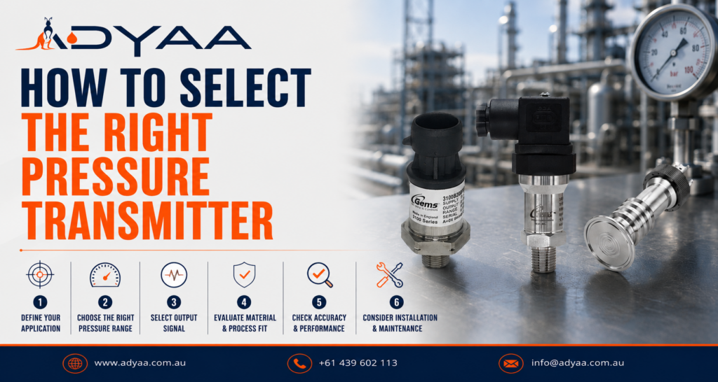
How to Select the Right Pressure Transmitter Pressure transmitters play a critical role in industrial automation, process control, water treatment, mining, manufacturing, and hydraulic systems. Selecting the correct pressure transmitter ensures accurate monitoring, improved equipment protection, and long-term operational reliability. Choosing the wrong sensor can result in inaccurate measurements, premature failures, increased maintenance costs, and process downtime. Understanding the key selection criteria helps engineers and maintenance teams achieve optimal performance from their pressure measurement systems. How to Select the Right Pressure Transmitter Understand the Required Pressure Range The first step in selecting a pressure transmitter is determining the operating pressure range of the application. A transmitter should typically operate within 30% to 80% of its full-scale range during normal conditions. Selecting an excessively large pressure range can reduce measurement accuracy, while choosing an undersized range can expose the sensor to overload conditions. Examples include: Water distribution systems: 0–10 bar Pump monitoring: 0–16 bar Hydraulic systems: 250–1000 bar Industrial compressors: 0–40 bar Always consider pressure spikes and transient conditions when selecting the final range. Choose the Correct Pressure Type Pressure transmitters are available in several measurement configurations: Gauge Pressure Measures pressure relative to atmospheric pressure and is commonly used in industrial processes. Absolute Pressure Measures pressure relative to a perfect vacuum and is often used in vacuum systems and scientific applications. Sealed Gauge Pressure References a fixed atmospheric pressure and is suitable for outdoor installations where environmental conditions vary. Selecting the correct pressure reference is essential for accurate process control. Consider Output Signal Requirements The transmitter output must be compatible with the control system or PLC. Common output signals include: 4–20 mA 0–5 V 0–10 V 1–5 V 1–10 V 0.5–4.5 V Ratiometric The 4–20 mA output remains the most widely used option due to its noise immunity and long-distance transmission capability. Evaluate Process Media Compatibility The wetted materials of the transmitter must be compatible with the process fluid. For demanding industrial environments, 316 Stainless Steel is commonly preferred due to its resistance to: Corrosion Chemical attack Moisture Process contamination Industries such as water treatment, food processing, chemical manufacturing, and mining often require robust stainless-steel construction. Check Environmental Conditions Industrial environments can expose pressure transmitters to: Vibration Hydraulic shock Temperature fluctuations Dust and moisture Chemical exposure Selecting a transmitter with suitable environmental protection improves reliability and service life. Applications involving hydraulic power units or heavy machinery may require sensors specifically designed to withstand pressure spikes and pulsation. Accuracy and Long-Term Stability Accuracy requirements vary between applications. General industrial processes typically use transmitters with accuracies between: ±0.5% Full Scale ±0.25% Full Scale Critical monitoring applications may require higher precision. Long-term stability is equally important as it reduces recalibration frequency and maintenance costs over the life of the equipment. Common Applications for Pressure Transmitters Pressure transmitters are widely used across industries including: Water Treatment Plants Mining Operations Hydraulic Systems Food and Beverage Processing Chemical Manufacturing Oil and Gas Facilities Industrial Automation Systems Pump and Compressor Monitoring Each application requires careful consideration of pressure range, output signal, material compatibility, and environmental conditions. Conclusion Selecting the right pressure transmitter involves more than simply matching a pressure range. Engineers should evaluate pressure type, output signal, process media compatibility, environmental conditions, and accuracy requirements to ensure reliable long-term performance. A properly selected pressure transmitter improves process efficiency, reduces maintenance costs, enhances equipment protection, and supports accurate industrial monitoring across a wide range of applications. Rupture Disc Operating Ratio Explained (Avoid Premature Failure) – Copy Rupture Disc Operating Ratio Explained (Avoid Premature Failure) Pressure transmitters play a critical role in industrial automation, process control, water… Read More → Rupture Disc Operating Ratio Explained (Avoid Premature Failure) Rupture Disc Operating Ratio Explained (Avoid Premature Failure) If your pressure relief devices are blowing during normal plant operations, you… Read More → Rupture Disc Selection Guide: 5 Critical Steps Rupture Disc Selection Guide: 5 Critical Steps Industrial plants cannot afford guesswork when it comes to overpressure protection. Picking a… Read More →
Rupture Disc Operating Ratio Explained (Avoid Premature Failure)
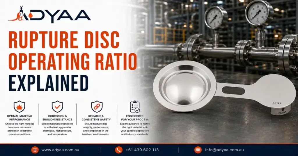
Rupture Disc Operating Ratio Explained (Avoid Premature Failure) If your pressure relief devices are blowing during normal plant operations, you are likely suffering from premature metal fatigue. This happens when your process runs too close to the disc’s breaking point. To prevent these expensive, nuisance shutdowns, you must strictly control your rupture disc operating ratio. Understanding this simple metric ensures you select a disc capable of surviving your daily pressure cycles without weakening. Quick Comparison: Allowable Ratios by Disc Design Rupture Disc Type Loading Type Max Operating Ratio Risk of Premature Fatigue Forward-Acting (Standard) Tension 70% to 80% High (if ratio is exceeded) Reverse-Acting (Buckling) Compression 90% to 95% Very Low Graphite Brittle / Shear 80% Moderate What is a Rupture Disc Operating Ratio? The rupture disc operating ratio is the mathematical relationship between your system’s everyday working pressure and the disc’s rated burst pressure. The Definition: It is the maximum percentage of the burst pressure that your system can safely operate at continuously. The Formula: Normal Operating Pressure ÷ Marked Burst Pressure = Operating Ratio. The Goal: To leave a wide enough safety buffer so the metal dome does not stretch, deform, or fatigue during normal daily pressure fluctuations. Why the “90% Rule” Matters for Plant Safety Engineers often refer to the “90% rule” when designing high-efficiency pipelines. Pushing past a disc’s specific ratio limit guarantees failure. Micro-Stretching: When pressure constantly pushes near a disc’s limit, the molecular structure of the metal begins to stretch irreversibly. Drifting Burst Pressures: A fatigued disc will no longer burst at its stamped rating. It will burst much lower, causing unexpected plant shutdowns. Pulsation Damage: If your pipeline features heavy pumps or compressors, the constant pulsing will accelerate metal fatigue even faster if your operating ratio is too tight. How Disc Engineering Alters the Ratio Not all discs can handle high operating ratios. You must match the mechanics to your process. Forward-Acting Limitations These discs face the process and stretch outward (tension loading). Because tension constantly weakens the metal, they are strictly limited to a 70% or 80% operating ratio. Reverse-Acting Advantages The dome faces against the process (compression loading). Metal resists compression incredibly well, allowing these discs to operate safely up to 90% or 95% of their burst pressure without fatiguing. How to Calculate and Apply the Ratio Do not guess your safety margins. Follow these exact steps to specify the right disc for your line: Step 1: Identify Normal Pressure. Determine the absolute highest pressure your system runs at during normal, non-emergency operations (e.g., 75 PSI). Step 2: Identify Burst Pressure. Determine the critical pressure where the disc must burst to save the vessel (e.g., 100 PSI). Step 3: Do the Math. 75 PSI ÷ 100 PSI = 0.75 (or a 75% ratio). Step 4: Make the Selection. Since 75% exceeds the safe limit of a standard forward-acting disc (usually 70%), you must upgrade to a reverse-acting disc to guarantee a long service life. FAQ – Rupture Disc Operating Ratio Q: What is a rupture disc operating ratio? A: It is the ratio between a system’s normal operating pressure and the disc’s rated burst pressure, expressed as a percentage. Q: What happens if I exceed the recommended operating ratio? A: The rupture disc will suffer from premature metal fatigue, stretching the dome and causing it to burst below its rated pressure during normal operations. Q: Can I operate a rupture disc at 100% of its burst pressure? A: No. Operating continuously at 100% guarantees immediate fatigue and premature failure. The absolute maximum for advanced designs is 95%. Q: Why do reverse-acting discs have higher operating ratios? A: Reverse-acting discs are loaded under compression rather than tension, making the metal highly resistant to stretching and fatigue. Q: Does system temperature affect the operating ratio? A: Yes. High temperatures weaken the metal, artificially lowering the burst pressure and effectively tightening your operating ratio. Q: What is the typical operating ratio for a graphite rupture disc? A: Most standard graphite rupture discs are rated for a maximum operating ratio of 80%. Secure Your Pressure Systems with ADYAA Stop wasting money on replacement discs due to premature fatigue. Designing the perfect pressure relief loop requires strict adherence to operating margins. As Australia’s premium industrial safety supplier, ADYAA provides high-ratio reverse-acting discs and expert engineering support to keep your facility running smoothly. Consult with ADYAA Reliability Experts Today Rupture Disc Operating Ratio Explained (Avoid Premature Failure) Rupture Disc Operating Ratio Explained (Avoid Premature Failure) If your pressure relief devices are blowing during normal plant operations, you… Read More → Rupture Disc Selection Guide: 5 Critical Steps Rupture Disc Selection Guide: 5 Critical Steps Industrial plants cannot afford guesswork when it comes to overpressure protection. Picking a… Read More → Guide to MNSB 53 for Fabrication Guide to MNSB 53 for Fabrication: Stop Moving Heavy Steel Let’s talk about the biggest bottleneck in a heavy fabrication… Read More →
Rupture Disc Selection Guide: 5 Critical Steps
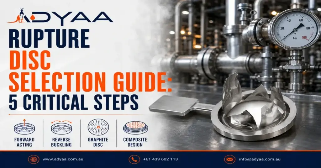
Rupture Disc Selection Guide: 5 Critical Steps Industrial plants cannot afford guesswork when it comes to overpressure protection. Picking a bursting disc out of a catalog based purely on flange size is a recipe for nuisance bursting, premature metal fatigue, or worse—a catastrophic failure to relieve pressure. A rupture disc is a precision-engineered life safety device. To ensure it activates exactly when your system reaches critical mass, you must match the metallurgy and mechanical design to the specific realities of your pipeline. Use this rupture disc selection guide to navigate the five essential engineering steps required to secure your facility. The 5 Steps of Rupture Disc Selection Step 1: Determine Burst Pressure and Coincident Temperature The most critical baseline is establishing your required burst pressure, but pressure never exists in a vacuum. You must define the coincident temperature—the exact temperature of the pipeline at the moment the overpressure event occurs. Because metal weakens as it gets hotter, a stainless steel disc calibrated to burst at 100 PSI at ambient temperature might burst prematurely at 80 PSI if the process runs at 200°C. You must provide your supplier with both variables so they can compensate for thermal weakening during the manufacturing process. Step 2: Calculate Your Operating Ratio Your operating ratio dictates whether you need a forward-acting or reverse-acting disc. This ratio is the gap between your normal operating pressure and your system’s Maximum Allowable Working Pressure (MAWP). Low Operating Ratio (Under 70%): If your system runs at 60 PSI and bursts at 100 PSI, a standard forward-acting disc is sufficient. High Operating Ratio (Up to 95%): If your system runs at 90 PSI and bursts at 100 PSI, a forward-acting disc will fatigue and fail. You must select a reverse-acting disc, which uses compression loading to handle tight pressure margins without degrading. Step 3: Assess Media and Material Compatibility A disc will not burst at its rated pressure if corrosive media has eaten away half its thickness. You must match the disc material to the chemical makeup of your process fluid or gas. Standard Media: 316 Stainless Steel or Nickel are industry standards for water, steam, and non-corrosive gases. Aggressive Media: For highly acidic or sour gas applications, you must upgrade to exotic alloys like Monel, Inconel, Hastelloy, or Tantalum. Extreme Corrosion: If metal cannot survive the environment, specify a graphite rupture disc, which is immune to most industrial solvents and acids. Step 4: Evaluate Downstream Conditions and Fragmentation Where is the pressure going once the disc bursts? If you are venting straight to the atmosphere, a standard fragmenting disc might be acceptable. However, if the disc is installed directly upstream of a mechanical safety relief valve, you must specify a non-fragmenting disc (like a reverse-buckling or cross-scored disc). If a standard disc shatters, the metal shrapnel will lodge in the safety valve, preventing it from closing. A Critical Note on Backpressure If your disc discharges into a common flare header or a closed manifold, you must account for superimposed backpressure. If there is 10 PSI of pressure pushing against the back of the disc, a 100 PSI disc will not burst until the internal system hits 110 PSI. In these scenarios, a balanced rupture disc design is required. Step 5: Select the Right Holder and Accessories A rupture disc is only as reliable as its installation. You cannot clamp a high-performance disc between two standard pipe flanges and expect it to work. You must select a dedicated rupture disc holder designed specifically for the disc profile (e.g., pre-torqued holders or insert-type holders). Additionally, consider integrating a burst indicator sensor that immediately alerts your SCADA system or control room the millisecond the disc activates. FAQ – Rupture Disc Selection Guide Q: What is the most important factor in rupture disc selection? A: Coincident temperature and burst pressure are the most critical, as the temperature directly alters the tensile strength and burst point of the metal. Q: When should I choose a reverse-acting rupture disc? A: Choose a reverse-acting disc when your normal operating pressure is 80% to 95% of your burst pressure, or when you are operating in a high-pulsation environment. Q: Do I need a non-fragmenting rupture disc? A: Yes, you must use a non-fragmenting disc if it is installed upstream of a safety relief valve or sensitive downstream equipment that could be damaged by metal shrapnel. Q: Can I install a rupture disc without a holder? A: No. Rupture discs require highly specific, precision-machined holders to ensure the correct seating, sealing, and bursting mechanics. Q: How does backpressure affect a rupture disc? A: Superimposed backpressure pushes against the downstream side of the disc, artificially raising the internal pressure required to burst it, unless a balanced disc is used. Q: What material is best for highly corrosive processes? A: For extreme chemical environments where stainless steel degrades, graphite, Hastelloy, or Tantalum are the preferred materials to ensure the burst pressure remains stable. Engineer Your Overpressure Protection with ADYAA Relying on a generic rupture disc selection guide is just the first step. Finalizing your safety systems requires exact engineering verification. As Australia’s leading supplier of industrial safety solutions, ADYAA provides ASME-certified rupture discs, precision holders, and thermal relief expertise to keep your plant safe and compliant. Consult with ADYAA Overpressure Experts Today Rupture Disc Operating Ratio Explained (Avoid Premature Failure) Rupture Disc Operating Ratio Explained (Avoid Premature Failure) If your pressure relief devices are blowing during normal plant operations, you… Read More → Rupture Disc Selection Guide: 5 Critical Steps Rupture Disc Selection Guide: 5 Critical Steps Industrial plants cannot afford guesswork when it comes to overpressure protection. Picking a… Read More → Guide to MNSB 53 for Fabrication Guide to MNSB 53 for Fabrication: Stop Moving Heavy Steel Let’s talk about the biggest bottleneck in a heavy fabrication… Read More →