
Burst Pressure Selection for Rupture Disc Safety

Burst Pressure Selection for Rupture Disc Safety When a pressurized system experiences an unexpected spike, your safety devices need to act instantly. A rupture disc is your facility’s last line of defense against catastrophic equipment failure. However, a disc is only as good as its specifications. Getting the Burst Pressure Selection for Rupture Disc Safety right is the difference between a safely controlled release and a critical plant emergency. As specialists in industrial safety and pressure relief systems, we frequently see facilities struggle with premature disc failures. Usually, it comes down to a misunderstanding of how operating pressures interact with disc ratings. Here is exactly how to navigate this selection process to protect your equipment. The Baseline: Operating Pressure vs. Burst Pressure You cannot select a rupture disc simply by looking at your normal daily pressure. You must understand the gap between your normal state and your danger zone. Operating Pressure: The pressure your system runs at during standard daily operations. Specified Burst Pressure: The exact pressure at which the manufacturer designs the disc to open. If your burst pressure is set too close to your operating pressure, minor everyday fluctuations will cause the disc to fatigue. This leads to premature bursting, costly downtime, and lost materials. 3 Core Factors of Burst Pressure Selection To achieve reliable Burst Pressure Selection for Rupture Disc Safety, you must calculate three specific variables. 1. Operating Ratio This is the relationship between your normal operating pressure and the disc’s marked burst pressure. Different designs handle different ratios. Standard Forward-Acting Discs: Typically require a 70% operating ratio. (e.g., If bursting at 100 PSI, operate no higher than 70 PSI). Reverse-Acting Discs: Can handle up to a 95% operating ratio. These are ideal for systems running close to the Maximum Allowable Working Pressure (MAWP). 2. Burst Tolerance No manufacturing process is perfect down to the micro-psi. Burst tolerance is the acceptable variation from the specified burst pressure. If you order a disc rated for 100 PSI with a +/- 5% tolerance, it might burst anywhere between 95 PSI and 105 PSI. Factoring in this margin of error is a critical step in Burst Pressure Selection for Rupture Disc Safety. You must ensure the lower end of the tolerance doesn’t overlap with regular pressure spikes. 3. Manufacturing Design Range (MDR) MDR is a standard agreement regarding where the final stamped burst pressure will fall relative to your requested pressure. Understanding MDR prevents surprises when the final product arrives at your plant. Real-World Example: Sizing for an Industrial Plant Imagine a chemical processing tank in an Australian facility with a MAWP of 200 PSI. The plant operates the tank normally at 160 PSI. Choosing a forward-acting disc (70% ratio) means they must drop operating pressure to 140 PSI. This hurts production. The Solution: By selecting a reverse-acting disc (90% ratio), they can set the burst pressure at 200 PSI and maintain their 160 PSI operation. This highlights why strategic Burst Pressure Selection for Rupture Disc Safety directly impacts both plant profitability and operational flow. The Impact of Temperature Temperature is the hidden variable that ruins poorly planned overpressure protection. As the temperature increases, the metal of the rupture disc weakens. A disc rated to burst at 100 PSI at room temperature will burst at a lower pressure if the system runs at 200°C. Conversely, extreme cold can strengthen the metal, delaying the burst. Specifying the exact coincident temperature is an absolute requirement for accurate Burst Pressure Selection for Rupture Disc Safety. People Also Ask (FAQs) Q: What is a safe operating ratio for rupture discs? A: It depends on the disc type. Forward-acting discs usually require a 70% ratio, while reverse-acting discs can safely operate up to 90% or 95% of the burst pressure. Q: Can temperature affect my rupture disc’s burst pressure? A: Yes. High temperatures weaken the disc material, causing it to burst at a lower pressure. Extreme cold can strengthen the metal and delay the burst. Q: Why do rupture discs burst prematurely? A: The most common cause is metal fatigue. This happens when the specified burst pressure is set too close to the daily operating pressure, causing the disc to weaken from normal system pulsations. The Bottom Line Upgrading your pressure relief systems requires looking at the entire environment—pressure cycles, vacuum conditions, fluid types, and temperature extremes. Skipping just one of these metrics compromises your entire safety infrastructure. Proper sizing prevents premature failures, avoids unexpected downtime, and guarantees regulatory compliance. Upgrade Your Plant Safety Today Need help finding the exact rupture disc for your facility’s unique conditions? Don’t leave your overpressure protection to guesswork. Explore our premium industrial safety solutions or contact the ADYAA Engineering Team today for expert sizing and selection. When to Replace Rupture Discs in Pressure Equipment: A Maintenance Guide – Copy Burst Pressure Selection for Rupture Disc Safety When a pressurized system experiences an unexpected spike, your safety devices need to… Read More → When to Replace Rupture Discs in Pressure Equipment: A Maintenance Guide When to Replace Rupture Discs in Pressure Equipment: A Maintenance Guide In the world of pressure safety, the rupture disc… Read More → Flange Sealing Solutions for High-Pressure Pipes: Zero Leakage Strategies Flange Sealing Solutions for High-Pressure Pipes: Zero Leakage Strategies In high-pressure industrial environments, the weakest link is rarely the pipe… Read More →
Pressure Transmitter Accuracy Explained: Reference vs. Real World
Decoding the Datasheet: The Truth About Pressure Transmitter Accuracy In the world of Industrial Pressure Sensors, “Accuracy” is the most expensive word on the datasheet. You see a shiny number like “±0.075%” printed in bold, and it’s natural to assume that’s exactly the error margin you’ll see on your control screen. But once you install that transmitter in the field—where it’s vibrating on a pump or baking in the Australian sun—the reality can be very different. This confusion leads to two common (and costly) mistakes: Over-specifying: Buying a Ferrari-level sensor for a go-kart application (wasting money). Under-specifying: Buying a cheap sensor that drifts constantly, ruining your process control. ADYAA, we believe the best customer is an educated one. So, let’s peel back the layers of the datasheet and explain what those accuracy specs actually mean for your plant. 1. The “Lab Number”: What Reference Accuracy Really Means The first number you see on a datasheet (e.g., ±0.075% of Span) is called Reference Accuracy. Think of this as the “Showroom Condition.” It tells you how the sensor performs in a perfect, air-conditioned laboratory with stable pressure and zero vibration. It is calculated using three specific test criteria, known as the “Big Three”: A. Linearity (The Straight Line) If you graph pressure vs. output signal, it should be a perfectly straight diagonal line. Linearity measures how much the sensor “wobbles” off that perfect path. If the linearity is bad, your DCS might say the tank is 50% full when it’s actually 51%. B. Hysteresis (The Memory Effect) Sensors have “muscle memory.” Going Up: You pressurize to 10 bar, and it reads 10.01 bar. Coming Down: You depressurize back to 10 bar, and it reads 9.99 bar. That difference is Hysteresis. It happens because the metal sensing diaphragm doesn’t snap back perfectly instantly. C. Repeatability (The Most Important Spec) If you hit the sensor with exactly 5 bar of pressure ten times in a row, does it give you the exact same number ten times? Repeatability is king. Even if a sensor is slightly off, if it’s repeatable, you can calibrate it to be perfect. If it’s not repeatable, it’s untrustworthy. The Reality Check: Reference Accuracy only tells you how good the sensor can be. It doesn’t tell you how good it will be in your plant. 2. The Real World: Why Accuracy Drops in the Field Your plant isn’t a laboratory. It’s hot, noisy, and dirty. These environmental factors introduce new errors that are not included in that headline “0.075%” number. Temperature Effect (The Sun Factor) Liquids expand when they get hot. Inside a Pressure Transmitter, there is a tiny amount of oil that transfers pressure to the sensor. The Problem: If your transmitter sits in the 40°C afternoon sun and then cools down to 10°C at night, that internal oil expands and contracts. This causes the “Zero” point to drift. The Fix: High-quality sensors use “Active Temperature Compensation” to mathematically correct this error in real-time. Cheap sensors do not. Static Pressure Effect This is a big one for Differential Pressure (DP) flow measurement. If you are measuring a tiny pressure drop across an orifice plate, but the pipe itself is pressurized to 50 bar, that massive static pressure squeezes the sensor body. This physical stress shifts the reading. 3. The Mistake: ignoring “Turndown Ratio” This is the most common reason we see “accurate” sensors giving bad data. Turndown Ratio is how much of the sensor’s range you are actually using. Accuracy is usually a percentage of the Maximum Range, not your calibrated set point. Scenario: You buy a sensor rated for 0-100 bar. The Mistake: You only use it to measure 0-5 bar. The Result: That tiny error margin at 100 bar becomes a huge error margin when you are only looking at 5 bar. Engineer’s Tip: Always buy a sensor range that is closest to your actual operating pressure. Don’t buy a 100 bar sensor to measure 5 bar “just in case.” 4. The “Real” Number: Total Probable Error (TPE) If you want to know the honest accuracy of a device, you need to calculate the Total Probable Error (TPE). This isn’t usually printed on the datasheet, but it’s the number that matters. It combines the Lab Accuracy with the Temperature and Static Pressure effects. Standard Sensor: Might claim 0.075% accuracy, but the real TPE is 0.25%. High-End Sensor: Might claim 0.04% accuracy, and the real TPE is 0.10%. Why does this matter? If you are calculating the efficiency of a million-dollar boiler, that difference is massive. 5. Which Sensor Tier Do You Actually Need? At ADYAA, we help you save money by matching the right tier to the right job. You don’t need a Porsche to drive to the grocery store. Tier 1: Standard Industrial (±0.25% – ±0.5%) Use for: Monitoring pumps, water tank levels, compressed air lines. Why: You just need to know if the pressure is stable. Close enough is good enough. Tier 2: Precision Process (±0.075%) Use for: Chemical reactors, steam flow, critical control loops. Why: A small error here could ruin a batch or waste energy. Tier 3: High Performance (±0.04% or better) Use for: Custody transfer (selling oil/gas), leak testing, calibration labs. Why: When every drop of product equals money, you pay for the best. Final Thoughts Don’t let the specs intimidate you. Understanding Pressure Transmitter Accuracy is simply about matching the tool to the environment. ADYAA can help you calculate the Total Probable Error for your specific application, ensuring you get a sensor that is accurate enough to keep you safe, without blowing your maintenance budget. Need help selecting the right pressure transmitter? 👉 Explore the ADYAA Pressure Range 📞 Contact us for a TPE Calculation. Industrial HVAC vs Commercial HVAC: What is the Difference? Industrial HVAC vs Commercial HVAC: Why Equipment Choice Matters If you walk onto the roof of a shopping mall and… Read More → How Industrial Automation Sensors Improve Manufacturing Efficiency How Industrial Automation Sensors Improve Efficiency in
Understanding Thermowells & Their Role in Process Instrumentation
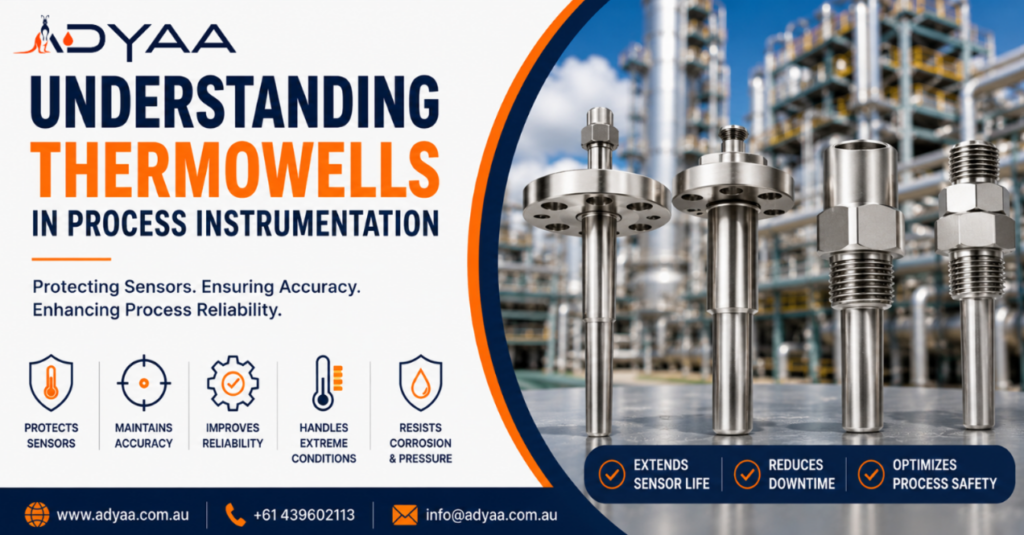
Understanding Thermowells and Their Role in Process Instrumentation In the vast ecosystem of process control, temperature is often the most critical variable. Whether you are refining crude oil, pasteurizing milk, or managing chemical reactions, accurate temperature data is non-negotiable. However, the sensors that measure this temperature—Resistance Temperature Detectors (RTDs) and Thermocouples—are often delicate devices. They contain fine wires and sensitive elements that would be destroyed instantly if exposed directly to high-velocity steam, corrosive acids, or abrasive slurries. Enter the Thermowell. Often overlooked as a simple metal fitting, the thermowell is actually a critical safety barrier. ADYAA, knows that selecting the wrong thermowell doesn’t just mean a broken sensor; it can lead to catastrophic vessel failure. In this guide, we break down everything you need to know about thermowells and their role in process instrumentation. What Is a Thermowell? A Thermowell is a cylindrical pressure-tight fitting that protects temperature sensors from the process media. Think of it as “armor” for your sensor. It is installed directly into the pipe or vessel, and the temperature sensor (the probe) is inserted into the open end of the thermowell. The heat transfers from the process fluid, through the thermowell wall, and into the sensor. The Three Primary Functions Protection: It isolates the fragile sensor from pressure, high velocity, and corrosion. Serviceability: This is arguably its most important role for operations. A thermowell allows you to remove and replace a faulty sensor without shutting down the process or draining the tank. Containment: It acts as a part of the process boundary. If the sensor is removed, the thermowell keeps the liquid or gas inside the pipe. Anatomy of a Thermowell: Stem Profiles Not all thermowells are simple tubes. The shape of the “stem” (the part immersed in the fluid) dictates how the well handles pressure and how fast it responds to temperature changes. 1. Straight Stem The same diameter along the entire immersion length. Pros: Strong and easy to manufacture. Cons: Slower response time due to more metal mass at the tip; susceptible to flow-induced vibration. 2. Stepped Stem The diameter is reduced (stepped down) at the tip where the sensor sits. Pros: Faster response time (less metal at the tip) and good strength. Cons: Slightly lower pressure rating than tapered. Verdict: The most common standard for general industry. 3. Tapered Stem The diameter gradually decreases from the root to the tip. Pros: The strongest design. It offers the best resistance to vibration and high-velocity flow. Cons: More expensive to machine. Verdict: Essential for high-velocity steam lines and heavy-duty petrochemical applications. Connection Types: How It Fits Your Process Threaded: Screws directly into the pipe. Low cost and easy to install, but not recommended for high pressure or flammable/hazardous materials due to the risk of leakage at the threads. Flanged: The thermowell is welded to a flange, which is bolted to a mating flange on the pipe. This is the standard for Oil & Gas and Chemical industries as it provides a secure, high-pressure seal. Socket Weld / Weld-In: Welded directly into the pipe wall. This is a permanent solution used for extremely high pressure (like steam generation) where no leakage path is permitted. The Hidden Danger: Wake Frequency and Vibration This is the most technical and critical part of thermowell selection. When fluid flows past a thermowell, it doesn’t just flow smoothly; it creates vortices (swirls) that shed from alternating sides of the stem. This is known as the Von Karman Vortex Street. These shedding vortices create oscillating forces that make the thermowell vibrate. The Risk: If the frequency of these vibrations matches the Natural Frequency of the thermowell (its resonant “sweet spot”), the thermowell will vibrate violently and snap off inside the pipe. The Result: The sensor is lost, and worse, you now have an open hole in your pipe spewing process fluid. The Solution: Always perform a Wake Frequency Calculation (per ASME PTC 19.3 TW-2016 standards) before installing thermowells in high-velocity lines. This calculation ensures the stem is thick enough and short enough to withstand the flow. Selecting the Right Material Since the thermowell is in direct contact with the media, material selection is vital to prevent corrosion. Stainless Steel (304/316): The industry standard for water, air, and mild chemicals. Monel / Hastelloy: Required for seawater or highly corrosive acids (Hydrochloric/Sulfuric). Inconel / Ceramic: Used for extremely high temperatures (furnaces and kilns) where steel would melt or oxidize. Conclusion: Small Component, Big Impact A thermowell might look like a simple piece of metal, but it is a highly engineered component that bridges the gap between delicate electronics and brutal industrial forces. Ignoring the details—like immersion length, material compatibility, or wake frequency—can lead to poor measurement accuracy or dangerous mechanical failures. ADYAA specialises in understanding that instrumentation isn’t just about reading a number on a screen; it’s about the safety and efficiency of your entire plant. Need help sizing the right thermowell for your application? Contact ADYAA’s Instrumentation Team Let us handle your Wake Frequency Calculations and material selection today. Industrial HVAC vs Commercial HVAC: What is the Difference? Industrial HVAC vs Commercial HVAC: Why Equipment Choice Matters If you walk onto the roof of a shopping mall and… Read More → How Industrial Automation Sensors Improve Manufacturing Efficiency How Industrial Automation Sensors Improve Efficiency in Manufacturing Efficiency is the primary metric of success. The difference between a profitable… Read More → Gems 3100/3200 Pressure Transmitters : Complete Guide – Copy Understanding Thermowells and Their Role in Process Instrumentation In the vast ecosystem of process control, temperature is often the most… Read More →
When to Replace Rupture Discs in Pressure Equipment: A Maintenance Guide
When to Replace Rupture Discs in Pressure Equipment: A Maintenance Guide In the world of pressure safety, the rupture disc is a “silent guardian.” It sits quietly in the pipework, waiting for the one bad day when pressure spikes dangerously high. Because it doesn’t move or chatter like a valve, it is easy to forget. However, forgetting this critical device is a dangerous gamble. Unlike a valve that can be tested and put back, a rupture disc has a finite lifespan. It suffers from fatigue, corrosion, and physical damage just like any other component. Knowing When to Replace Rupture Discs is the key to preventing two major headaches: nuisance bursts (which stop production) and failure to open (which risks an explosion). 1. After Any Overpressure Event This is the golden rule: If a disc bursts, it must be replaced. But you must also check the discs that didn’t burst. If your system experienced a pressure spike that came close to the burst pressure (e.g., within 95% of the limit) but didn’t quite pop the disc, the metal membrane may still be stressed. The crystalline structure of the metal can stretch and weaken. If you leave it in service, it will likely fail prematurely later on during normal operation. 2. During Scheduled Maintenance (The “Best Before” Date) Rupture discs are not permanent fixtures. Manufacturers provide a recommended service life based on the material and the design. Standard Practice: Many plants proactively replace discs every 12 to 24 months during major shutdowns. Why? The cost of a new disc is tiny compared to the cost of an unscheduled plant shutdown caused by an old, fatigued disc bursting on a Tuesday afternoon. 3. If You See Corrosion or Pitting Visual inspection is your best friend. During a shutdown, if you inspect the disc and see: Pitting: Small holes or rough spots on the surface. Discoloration: Signs of chemical attack. Buildup: Product caking on the face of the disc. Then it is time to replace it immediately. Even microscopic corrosion thins the metal, which lowers the burst pressure.A disc designed for 100 PSI may fail at 80 PSI if corrosion has reduced its thickness by 20%. 4. After Installation Errors (The “Torque Trap”) This is a common, silent killer of discs. If a technician installs a disc, torques the flange bolts, and then realizes they need to loosen them to adjust alignment, the disc is ruined. Once a metal disc has been compressed (bited) into the holder, loosening and re-tightening creates stress fractures and potential leak paths. If a disc is ever removed or loosened for any reason, the rule on When to Replace Rupture Discs is simple: throw it away and install a fresh one. 5. When Process Conditions Change Did you increase the operating temperature of the vessel? Did you switch from a static load to a pulsating pump? Temperature: Burst pressure drops as temperature rises. A disc that was safe at 50°C might be dangerously weak at 150°C. Cycling: Rapid pressure cycling (pulsation) fatigues metal quickly. If you change the process to a high-cycling application, you may need to switch to a specialized “reverse buckling” disc designed to handle fatigue, rather than just replacing the old one with the same model. Bottom Line A rupture disc is a precision instrument, not a simple piece of metal. It is calibrated to save lives. Determining when to Replace Rupture Discs shouldn’t be a guessing game. It should be a scheduled part of your asset integrity program. Replacing a disc a month early costs a few dollars; replacing it one second too late costs everything. Is your plant due for a safety review? Stop relying on potentially fatigued equipment. Let our team help you establish a reliable replacement schedule. Contact ADYAA Pressure Safety Team Get advice on disc lifecycles and preventative maintenance. When to Replace Rupture Discs in Pressure Equipment: A Maintenance Guide When to Replace Rupture Discs in Pressure Equipment: A Maintenance Guide In the world of pressure safety, the rupture disc… Read More → Flange Sealing Solutions for High-Pressure Pipes: Zero Leakage Strategies Flange Sealing Solutions for High-Pressure Pipes: Zero Leakage Strategies In high-pressure industrial environments, the weakest link is rarely the pipe… Read More → How to Select Pressure Relief Valves for Industrial Plants How to Select Pressure Relief Valves for Industrial Plants If a pump fails, production stops. If a control valve fails,… Read More →
Flange Sealing Solutions for High-Pressure Pipes: Zero Leakage Strategies
Flange Sealing Solutions for High-Pressure Pipes: Zero Leakage Strategies In high-pressure industrial environments, the weakest link is rarely the pipe itself it is the connection point. When you are moving steam at 100 bar or processing hydrocarbons at extreme temperatures, a standard gasket isn’t just a seal; it is a critical safety barrier. A failed flange seal leads to more than just a hiss of escaping steam. It causes unplanned shutdowns, environmental fines, and safety hazards for personnel. To prevent blowout, engineers must move beyond ‘off-the-shelf’ gaskets and engineer specific Flange Sealing Solutions for High-Pressure Pipes that can withstand the immense forces at play. The Challenge of High Pressure Why do high-pressure seals fail? It usually boils down to three forces fighting against the gasket: Internal Pressure: The fluid tries to push the gasket out of the flange (blowout force). Bolt Stretch: High pressure tries to separate the flange faces, reducing the compression load on the gasket. Thermal Cycling: Rapid heating and cooling cause the metal flanges to expand and contract, often crushing the gasket or leaving it loose. Effective High-Pressure Gaskets must maintain their seal integrity despite these aggressive dynamics. 1. Metallic Gaskets: The Standard for Strength For ASME Class 900 flanges and above, soft gaskets (like rubber or PTFE) are simply not an option. You need metal to hold the pressure. Ring Type Joints (RTJ) This is the gold standard for the oil and gas industry. An RTJ Gasket is a solid metal ring (typically soft iron or stainless steel) that sits inside a groove machined into the flange face. How it works: When bolted down, the harder flange wedges the softer metal ring into the groove, creating a metal-to-metal seal that gets tighter as internal pressure increases. Best For: Extreme pressure (up to 20,000 psi) and high-temperature applications. Spiral Wound Gaskets (SWG) The most versatile high-pressure solution. It consists of a metal winding (usually stainless steel) filled with a soft material like flexible graphite. How it works: The metal winding provides structural strength and blowout resistance, while the graphite filler fills the microscopic imperfections on the flange face to create a seal. The Critical Component: For high pressure, always choose an SWG with an Inner Ring. This ring protects the sealing element from the turbulent flow of the fluid and prevents the gasket from buckling inward. 2. Kammprofile Gaskets: The Problem Solver When you have older flanges with pitted or damaged surfaces, or you need to seal a heat exchanger, the Kammprofile Gasket (or Camprofile) is the superior choice among Flange Sealing Solutions for High-Pressure Pipes. It features a solid metal core with serrated grooves on both sides, covered by a soft facing layer (Graphite or PTFE). The serrations concentrate the bolt load into small areas, creating a massive amount of sealing stress with relatively low bolt torque. This makes them ideal for vintage equipment where you cannot over-torque the bolts without damaging the flange. 3. Installation: Where Most Seals Fail You can buy the most expensive RTJ Gasket on the market, but if it is installed poorly, it will leak. Torque Control: Using a torque wrench is mandatory. Uneven tightening warps the gasket. Flange Condition: High-pressure seals require a specific surface finish. An RTJ groove must be mirror-smooth, while a Spiral Wound gasket needs a specific roughness to ‘bite’ into. Lubrication: Friction on the bolt threads steals torque. Using a high-quality lubricant ensures that the force you apply actually compresses the gasket. The Bottom Line A leak at 10 psi is a nuisance. A leak at 10,000 psi is a catastrophe. Selecting the right Flange Sealing Solutions for High-Pressure Pipes requires balancing the pressure rating, the chemical compatibility, and the mechanical condition of your flanges. Whether it is a robust Ring Type Joint for a wellhead or a precision Kammprofile for a reactor, the goal is always the same: zero emissions, zero downtime. Are your high-pressure connections secure? Don’t guess with gasket selection. Let our sealing experts review your application parameters. Explore ADYAA’s Industrial Sealing Range. Contact us for technical advice on high-pressure gaskets. Recent Posts When to Replace Rupture Discs in Pressure Equipment: A Maintenance Guide When to Replace Rupture Discs in Pressure Equipment: A Maintenance Guide In the world of pressure safety, the rupture disc… Read More → Flange Sealing Solutions for High-Pressure Pipes: Zero Leakage Strategies Flange Sealing Solutions for High-Pressure Pipes: Zero Leakage Strategies In high-pressure industrial environments, the weakest link is rarely the pipe… Read More → How to Select Pressure Relief Valves for Industrial Plants How to Select Pressure Relief Valves for Industrial Plants If a pump fails, production stops. If a control valve fails,… Read More →
How to Select Pressure Relief Valves for Industrial Plants
How to Select Pressure Relief Valves for Industrial Plants If a pump fails, production stops. If a control valve fails, the process drifts. But if a pressure relief valve (PRV) fails, people can get hurt. Selecting the right safety device is not just about matching a pipe size. It is an engineering discipline that sits at the intersection of fluid dynamics, thermodynamics, and mechanical integrity. A valve that is too small won’t relieve pressure fast enough to prevent an explosion. A valve that is too big will “chatter”, destroying its own seat and causing leaks within seconds. We see many facilities struggle with this complex choice. In this guide, we break down the critical engineering factors you must evaluate when choosing Pressure Relief Valves for industrial plants. 1. Know Your Fluid State (Gas, Liquid, or Steam?) The first question isn’t “what pressure?”—it is “what phase?” A valve designed for incompressible liquid (like water) behaves very differently from one designed for compressible gas (like nitrogen or steam). For Gases/Steam: You typically need a valve that “pops” open instantly to release maximum volume. For Liquids: You often need a relief valve designed for “trim” opening to prevent water hammer (a sudden pressure shockwave) that can rupture pipes. The Rule: Never swap a liquid-trim valve for a gas-service valve without consulting a specialist. The flow characteristics are fundamentally different. 2. The “Hidden” Factor: Back Pressure This is the most common trap in PRV selection. When a valve opens, it usually vents into a discharge header pipe that is collected with other valves. This pipe might already have pressure in it from other processes. This is called Back Pressure. Ideally suited for when venting directly to the atmosphere. However, if there is variable back pressure in the discharge pipe, it pushes against the valve disc, changing the set pressure. This makes the valve unreliable. Balanced Bellows PRVs: These contain a metal bellow that shields the moving parts from back pressure. If your discharge header pressure fluctuates, you must select a balanced bellows design. Pilot-Operated PRVs: For extremely high back pressures or when you need to operate very close to the set pressure, a pilot valve uses the system pressure itself to keep the valve sealed tight until the exact moment it needs to open. 3. Temperature and Material Compatibility Selecting Pressure Relief Valves for industrial plants requires a deep look at the material compatibility table. Standard Carbon Steel bodies (WCB) are fine for general utilities. However, if you are handling corrosive acids, sour gas (H₂S), or cryogenic fluids (LNG), standard materials will fail. High Temperature: Chrome-moly steels may be required to prevent metal creep. Low Temperature: Stainless steel (316) is often needed to prevent brittle fracture in cold climates or cryogenic services. Tip: Always specify if your valve needs NACE compliance (for sour gas environments) to prevent sudden cracking of the valve body. 4. Sizing: The “Goldilocks” Principle Sizing is where the math happens (specifically, API 520 calculations). Undersized: The valve opens, but pressure continues to rise because the valve can’t vent fluid fast enough. Result: Vessel failure. Oversized: The valve opens, vents too fast, pressure drops instantly, the valve slams shut, pressure rises again, and the valve pops open again. This rapid “chatter” destroys the valve internals and flange faces. You need a valve that is sized exactly for your required relieving capacity—no more, no less. 5. Connection Types and Standards Are you following API 526? This standard dictates the flange dimensions and center-to-face measurements. Why it matters: If you select an API 526 compliant valve, you know that years from now, you can swap it out with another brand’s API 526 valve and it will fit perfectly into the same pipe gap. It future-proofs your facility. Conclusion: Trust the Specialists There is no “off-the-shelf” solution for safety. Every PRV must be sized and selected for the specific tag number it serves. ADYAA sells valves and calculates them. Our engineering team reviews your process conditions against the latest standards to ensure your Pressure Relief Valves for industrial plants will perform when the alarm bells start ringing. Unsure if your current valves are sized correctly? Contact ADYAA for a Pressure Relief Audit. Speak to our technical team about API 520 sizing today. When to Replace Rupture Discs in Pressure Equipment: A Maintenance Guide When to Replace Rupture Discs in Pressure Equipment: A Maintenance Guide In the world of pressure safety, the rupture disc… Read More → Flange Sealing Solutions for High-Pressure Pipes: Zero Leakage Strategies Flange Sealing Solutions for High-Pressure Pipes: Zero Leakage Strategies In high-pressure industrial environments, the weakest link is rarely the pipe… Read More → How to Select Pressure Relief Valves for Industrial Plants How to Select Pressure Relief Valves for Industrial Plants If a pump fails, production stops. If a control valve fails,… Read More →