
Burst Pressure Temperature Calculation: A Definitive Guide
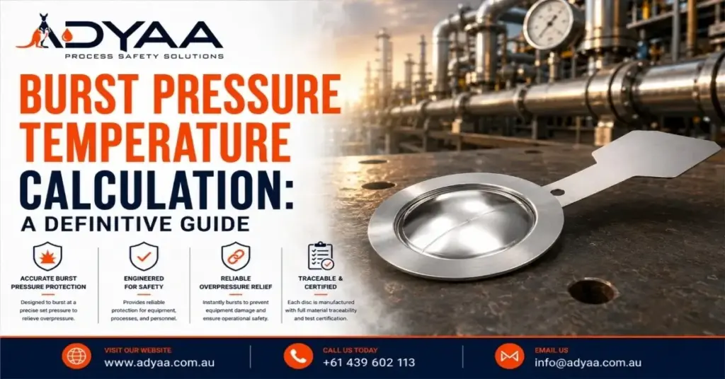
Burst Pressure Temperature Calculation: A Definitive Guide When designing an overpressure protection system, specifying a rupture disc based solely on ambient temperature is a dangerous engineering oversight. The tensile strength of metals and graphite changes drastically as temperatures rise. If a process spikes to 400°C, the disc will burst far below its stamped rating, leading to nuisance bursting, process downtime, and lost product. To guarantee that your safety systems activate exactly at your Maximum Allowable Working Pressure (MAWP), engineers must perform a precise burst pressure temperature calculation. This guide breaks down the core physics, the derating formulas, and how to apply them to real-world industrial pipelines. Quick Reference: Thermal Limits of Common Disc Materials Material Max Operating Temp (°C) Temperature Sensitivity 316 Stainless Steel ~480°C Strength reduces significantly at elevated temperature Nickel 200 ~400°C Good thermal resistance Monel 400 ~430°C Stable in moderate high-temperature service Inconel 600 ~590°C+ Excellent high-temperature stability Graphite ~200°C (Standard) Very thermally stable until oxidation/degradation Understanding Coincident Temperature In overpressure engineering, you cannot separate pressure from heat. The coincident temperature is defined as the exact expected temperature of the disc material at the exact moment the burst pressure is reached. Because industrial rupture discs are precision-calibrated membranes, heat expands their molecular structure, lowering the amount of physical force (pressure) required to tear or buckle the dome. Therefore, a rupture disc rated to burst at 100 PSI at 20°C may rupture at a lower pressure, such as around 85 PSI, when exposed to elevated operating temperatures like 250°C due to the reduction in material strength at higher temperatures. (Note: Actual reduction depends on disc material, thickness, manufacturing method, and ASME temperature correction factors. ) The Core Formula for Temperature Derating To find the actual burst pressure of a disc at an elevated temperature, manufacturers use a temperature correction factor (often referred to as a derating factor). The foundational burst pressure temperature calculation is: PT=PA×CF Where: PT = corrected burst pressure at operating temperature PA = burst pressure at ambient/reference temperature CF = temperature correction factor Example: If: PA =100 PSI CF =0.85 Then: PT =100×0.85=85 PSI Note: While engineers use this formula for estimations, rupture disc manufacturers test batches of material in thermal chambers to establish exact, certified curves for every specific lot. How Material Selection Impacts Burst Pressure Calculations If the operating or coincident temperature fluctuates significantly, highly temperature-sensitive materials such as Stainless Steel or Aluminum may experience greater variation in burst pressure due to the reduction in mechanical strength at elevated temperatures. To improve burst pressure stability across varying temperatures, higher-performance materials are often selected: Inconel 600: This nickel-chromium superalloy retains its mechanical strength exceptionally well at elevated temperatures. Its temperature correction curve is relatively stable, making it suitable for high-temperature steam, refinery, and petrochemical applications. Graphite: Resin-impregnated graphite rupture discs exhibit excellent thermal stability and are less affected by thermal softening compared to metallic discs. Within their recommended operating range, the temperature correction effect is often minimal for many standard applications. FAQ – Burst Pressure Temperature Calculation Q: What is coincident temperature? A: Coincident temperature is the exact physical temperature of the rupture disc material at the exact moment it is required to burst. Q: Why does a rupture disc burst at a lower pressure when hot? A: Heat alters the molecular structure of the metal, lowering its tensile and yield strength, meaning less pressure is required to tear or buckle the dome. Q: Can I calculate the exact temperature correction factor myself? A: No. While you can estimate it, the exact correction factor varies by the specific batch of raw material and must be certified by the manufacturer through destructive thermal testing. Q: What material should I use for highly fluctuating temperatures? A: Inconel 600 is highly recommended for fluctuating high-temperature environments because its tensile strength remains remarkably stable compared to standard stainless steel. Q: How does cold temperature affect burst pressure? A: Extreme cold (cryogenic temperatures) increases the tensile strength of the metal, which will artificially raise the burst pressure, requiring a reverse temperature calculation. Q: Do graphite rupture discs need temperature correction? A: Generally, no. Graphite remains physically stable and its burst pressure does not fluctuate significantly with heat, provided it stays below the thermal limit of its resin binder. Engineer Your Overpressure Protection with ADYAA Precision engineering leaves zero room for error. Calculating the thermal impact on your safety devices requires exact metallurgical data and certified manufacturing. As Australia’s leading supplier of industrial safety solutions, ADYAA provides fully tested, ASME-certified rupture discs calibrated for your exact coincident temperatures. Consult with ADYAA Overpressure Experts Today Rupture Disc Material Selection Guide for Harsh Processes Rupture Disc Maintenance and Inspection Checklist If you pump highly corrosive acids or superheated steam through a standard stainless steel… Read More → Rupture Disc Maintenance and Inspection Checklist Rupture Disc Maintenance and Inspection Checklist Treating a rupture disc as a “set it and forget it” device is a… Read More → Types of Rupture Discs: Complete Guide to All Designs Types of Rupture Discs: Complete Guide to All Designs Pressure systems are unpredictable. When a mechanical safety valve freezes or… Read More →
Protecting Equipment with Pressure Relief Systems
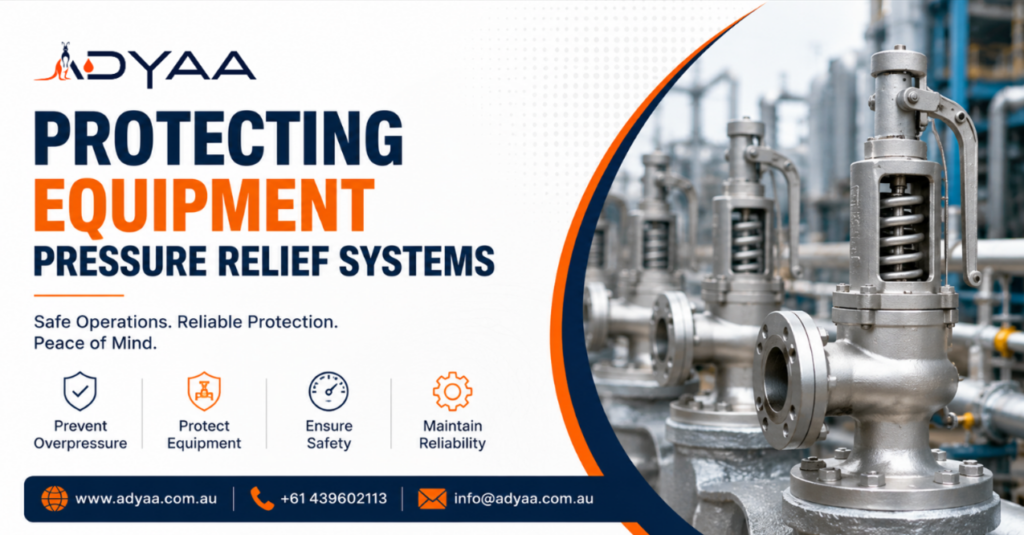
Protecting Equipment with Pressure Relief Systems: A Plant Manager’s Guide Industrial assets are expensive. A single reactor or distillation column represents millions of dollars in capital investment, not to mention the revenue it generates every hour it is online. Yet, these massive steel giants have a weakness: they are incredibly sensitive to internal pressure limits. If a control loop fails or a cooling system stalls, internal pressure can rise within seconds. Without a reliable escape path, the vessel walls will yield, leading to catastrophic equipment damage, environmental release, or safety hazards. Protecting Equipment with Pressure Relief Systems is not just about meeting a compliance checklist; it is the fundamental insurance policy for your plant’s physical assets. The Hidden Mechanisms of Failure To understand how to protect your machinery, you first need to understand the enemy. Overpressure events rarely happen without warning, but they often happen too fast for human intervention. Common culprits include: Blocked Discharge: A valve is accidentally closed downstream while a pump continues to run, dead-heading the flow and spiking pressure. External Fire: A fire near a storage tank causes the liquid inside to boil, expanding rapidly into gas and overwhelming the vessel’s design limits. Thermal Expansion: A pipeline full of liquid is isolated and heated by the sun, causing the fluid to expand and rupture the pipe. In all these scenarios, the vessel integrity depends entirely on the mechanical response of your relief system. The Hierarchy of Defense Effective protection isn’t about slapping a valve on a tank. It requires a layered engineering strategy. When Protecting Equipment with Pressure Relief Systems, we typically look at two distinct lines of defence: 1. The Reclosing Barrier (Safety Valves) The Safety Relief Valve (SRV) is the primary defender. Its job is to open at a set pressure, release just enough fluid to restore safety, and then close again. This protects the equipment from rupturing while simultaneously attempting to save the remaining product in the tank. It is the “recoverable” safety measure. 2. The Ultimate Fail-Safe (Rupture Discs) Some threats are too fast or too corrosive for a standard valve. A rupture disc is a non-reclosing device that bursts open instantly. It is often used to isolate expensive safety valves from corrosive chemicals or to provide a massive, unrestricted vent path during an explosion. Engineering for Reliability, Not Just Compliance Many facilities make the mistake of sizing a relief valve once, installing it, and forgetting it for five years. However, Protecting Equipment with Pressure Relief Systems is a dynamic process that evolves with your plant. Precision Sizing is Critical A common misconception is that “bigger is safer.” This is false. Oversized Valves: If a valve is too large for the required flow, it will open and close rapidly (chatter). This violent hammering can damage the valve seat and the vessel flange itself. Undersized Valves: These cannot vent pressure fast enough to keep up with the generation rate (e.g., during a fire), leading to vessel failure. Proper protection requires rigorous calculations (often using API 520 standards) to ensure the valve matches the specific hydraulic reality of the process. The Role of Back Pressure You must also consider where the fluid goes. If you vent into a header system shared by other units, the pressure in that header pushes back against your valve. If you don’t account for this “back pressure” by using balanced bellows or pilot-operated valves, your protection system may not open when it’s supposed to. The Shift to Data-Driven Maintenance Old-school maintenance involved pulling every valve every year for testing. This is costly and introduces unnecessary risk (damage during handling). Modern asset protection relies on Risk-Based Inspection (RBI). By analysing the history and service conditions of each valve, you can determine which equipment is high-risk and needs frequent attention, and which can safely operate for longer intervals. This approach ensures your resources are focused exactly where the equipment needs them most. The Bottom Line Your pressure vessels are the heart of your operation. A compromise in their integrity is a compromise in your business’s future. Protecting Equipment with Pressure Relief Systems requires more than just hardware; it demands correct engineering, proper material selection, and a maintenance strategy based on data, not guesswork. Ensuring your valves and discs are correctly sized and maintained is the only way to guarantee that when the pressure rises, your assets remain safe. Is your facility protected against the unexpected? Let our engineering team audit your current relief sizing and maintenance strategy to ensure your assets are secure. Contact ADYAA Engineering Speak to a specialist today about optimizing your pressure safety strategy. Industrial HVAC vs Commercial HVAC: What is the Difference? Industrial HVAC vs Commercial HVAC: Why Equipment Choice Matters If you walk onto the roof of a shopping mall and… Read More → How Industrial Automation Sensors Improve Manufacturing Efficiency How Industrial Automation Sensors Improve Efficiency in Manufacturing Efficiency is the primary metric of success. The difference between a profitable… Read More → Gems 3100/3200 Pressure Transmitters : Complete Guide Gems 3100/3200 Pressure Transmitters: Complete Guide Accurate pressure monitoring is essential across industrial environments where process visibility, operational consistency and… Read More →