When to Replace Rupture Discs in Pressure Equipment: A Maintenance Guide
When to Replace Rupture Discs in Pressure Equipment: A Maintenance Guide In the world of pressure safety, the rupture disc is a “silent guardian.” It sits quietly in the pipework, waiting for the one bad day when pressure spikes dangerously high. Because it doesn’t move or chatter like a valve, it is easy to forget. However, forgetting this critical device is a dangerous gamble. Unlike a valve that can be tested and put back, a rupture disc has a finite lifespan. It suffers from fatigue, corrosion, and physical damage just like any other component. Knowing When to Replace Rupture Discs is the key to preventing two major headaches: nuisance bursts (which stop production) and failure to open (which risks an explosion). 1. After Any Overpressure Event This is the golden rule: If a disc bursts, it must be replaced. But you must also check the discs that didn’t burst. If your system experienced a pressure spike that came close to the burst pressure (e.g., within 95% of the limit) but didn’t quite pop the disc, the metal membrane may still be stressed. The crystalline structure of the metal can stretch and weaken. If you leave it in service, it will likely fail prematurely later on during normal operation. 2. During Scheduled Maintenance (The “Best Before” Date) Rupture discs are not permanent fixtures. Manufacturers provide a recommended service life based on the material and the design. Standard Practice: Many plants proactively replace discs every 12 to 24 months during major shutdowns. Why? The cost of a new disc is tiny compared to the cost of an unscheduled plant shutdown caused by an old, fatigued disc bursting on a Tuesday afternoon. 3. If You See Corrosion or Pitting Visual inspection is your best friend. During a shutdown, if you inspect the disc and see: Pitting: Small holes or rough spots on the surface. Discoloration: Signs of chemical attack. Buildup: Product caking on the face of the disc. Then it is time to replace it immediately. Even microscopic corrosion thins the metal, which lowers the burst pressure.A disc designed for 100 PSI may fail at 80 PSI if corrosion has reduced its thickness by 20%. 4. After Installation Errors (The “Torque Trap”) This is a common, silent killer of discs. If a technician installs a disc, torques the flange bolts, and then realizes they need to loosen them to adjust alignment, the disc is ruined. Once a metal disc has been compressed (bited) into the holder, loosening and re-tightening creates stress fractures and potential leak paths. If a disc is ever removed or loosened for any reason, the rule on When to Replace Rupture Discs is simple: throw it away and install a fresh one. 5. When Process Conditions Change Did you increase the operating temperature of the vessel? Did you switch from a static load to a pulsating pump? Temperature: Burst pressure drops as temperature rises. A disc that was safe at 50°C might be dangerously weak at 150°C. Cycling: Rapid pressure cycling (pulsation) fatigues metal quickly. If you change the process to a high-cycling application, you may need to switch to a specialized “reverse buckling” disc designed to handle fatigue, rather than just replacing the old one with the same model. Bottom Line A rupture disc is a precision instrument, not a simple piece of metal. It is calibrated to save lives. Determining when to Replace Rupture Discs shouldn’t be a guessing game. It should be a scheduled part of your asset integrity program. Replacing a disc a month early costs a few dollars; replacing it one second too late costs everything. Is your plant due for a safety review? Stop relying on potentially fatigued equipment. Let our team help you establish a reliable replacement schedule. 👉 Contact ADYAA Pressure Safety Team 📞 Get advice on disc lifecycles and preventative maintenance. When to Replace Rupture Discs in Pressure Equipment: A Maintenance Guide When to Replace Rupture Discs in Pressure Equipment: A Maintenance Guide In the world of pressure safety, the rupture disc… Read More → Flange Sealing Solutions for High-Pressure Pipes: Zero Leakage Strategies Flange Sealing Solutions for High-Pressure Pipes: Zero Leakage Strategies In high-pressure industrial environments, the weakest link is rarely the pipe… Read More → How to Select Pressure Relief Valves for Industrial Plants How to Select Pressure Relief Valves for Industrial Plants If a pump fails, production stops. If a control valve fails,… Read More →
How to Select Pressure Relief Valves for Industrial Plants
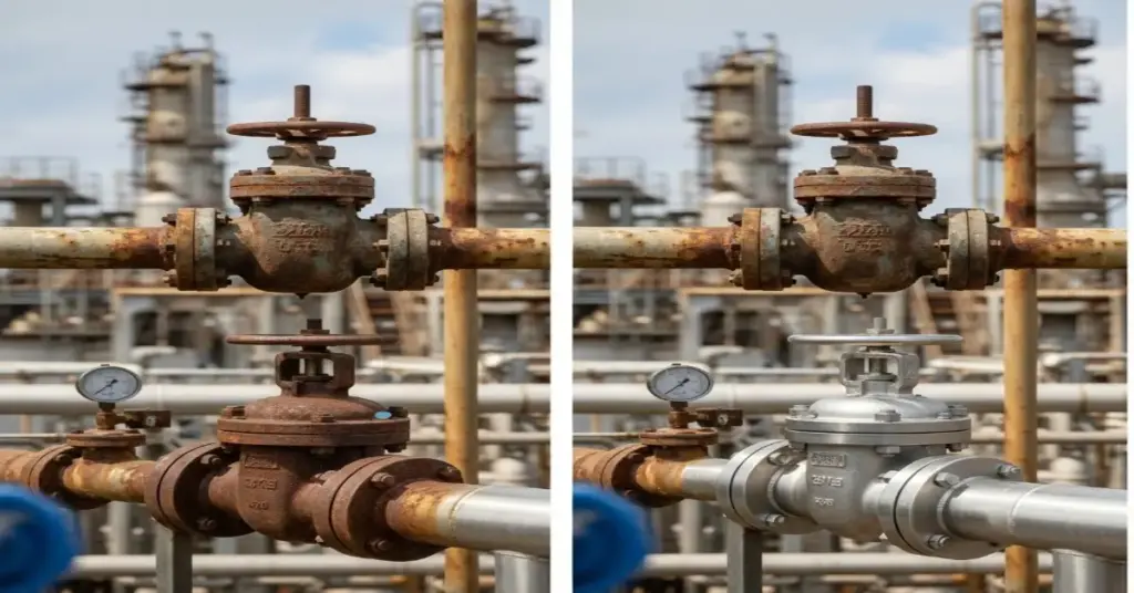
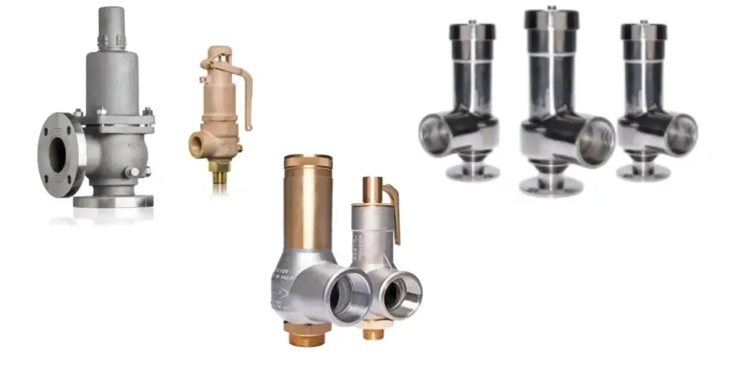
How to Select Pressure Relief Valves for Industrial Plants If a pump fails, production stops. If a control valve fails, the process drifts. But if a pressure relief valve (PRV) fails, people can get hurt. Selecting the right safety device is not just about matching a pipe size. It is an engineering discipline that sits at the intersection of fluid dynamics, thermodynamics, and mechanical integrity. A valve that is too small won’t relieve pressure fast enough to prevent an explosion. A valve that is too big will “chatter”, destroying its own seat and causing leaks within seconds. We see many facilities struggle with this complex choice. In this guide, we break down the critical engineering factors you must evaluate when choosing Pressure Relief Valves for industrial plants. 1. Know Your Fluid State (Gas, Liquid, or Steam?) The first question isn’t “what pressure?”—it is “what phase?” A valve designed for incompressible liquid (like water) behaves very differently from one designed for compressible gas (like nitrogen or steam). For Gases/Steam: You typically need a valve that “pops” open instantly to release maximum volume. For Liquids: You often need a relief valve designed for “trim” opening to prevent water hammer (a sudden pressure shockwave) that can rupture pipes. The Rule: Never swap a liquid-trim valve for a gas-service valve without consulting a specialist. The flow characteristics are fundamentally different. 2. The “Hidden” Factor: Back Pressure This is the most common trap in PRV selection. When a valve opens, it usually vents into a discharge header pipe that is collected with other valves. This pipe might already have pressure in it from other processes. This is called Back Pressure. Ideally suited for when venting directly to the atmosphere. However, if there is variable back pressure in the discharge pipe, it pushes against the valve disc, changing the set pressure. This makes the valve unreliable. Balanced Bellows PRVs: These contain a metal bellow that shields the moving parts from back pressure. If your discharge header pressure fluctuates, you must select a balanced bellows design. Pilot-Operated PRVs: For extremely high back pressures or when you need to operate very close to the set pressure, a pilot valve uses the system pressure itself to keep the valve sealed tight until the exact moment it needs to open. 3. Temperature and Material Compatibility Selecting Pressure Relief Valves for industrial plants requires a deep look at the material compatibility table. Standard Carbon Steel bodies (WCB) are fine for general utilities. However, if you are handling corrosive acids, sour gas (H₂S), or cryogenic fluids (LNG), standard materials will fail. High Temperature: Chrome-moly steels may be required to prevent metal creep. Low Temperature: Stainless steel (316) is often needed to prevent brittle fracture in cold climates or cryogenic services. Tip: Always specify if your valve needs NACE compliance (for sour gas environments) to prevent sudden cracking of the valve body. 4. Sizing: The “Goldilocks” Principle Sizing is where the math happens (specifically, API 520 calculations). Undersized: The valve opens, but pressure continues to rise because the valve can’t vent fluid fast enough. Result: Vessel failure. Oversized: The valve opens, vents too fast, pressure drops instantly, the valve slams shut, pressure rises again, and the valve pops open again. This rapid “chatter” destroys the valve internals and flange faces. You need a valve that is sized exactly for your required relieving capacity—no more, no less. 5. Connection Types and Standards Are you following API 526? This standard dictates the flange dimensions and center-to-face measurements. Why it matters: If you select an API 526 compliant valve, you know that years from now, you can swap it out with another brand’s API 526 valve and it will fit perfectly into the same pipe gap. It future-proofs your facility. Conclusion: Trust the Specialists There is no “off-the-shelf” solution for safety. Every PRV must be sized and selected for the specific tag number it serves. ADYAA sells valves and calculates them. Our engineering team reviews your process conditions against the latest standards to ensure your Pressure Relief Valves for industrial plants will perform when the alarm bells start ringing. Unsure if your current valves are sized correctly? Contact ADYAA for a Pressure Relief Audit. Speak to our technical team about API 520 sizing today. When to Replace Rupture Discs in Pressure Equipment: A Maintenance Guide When to Replace Rupture Discs in Pressure Equipment: A Maintenance Guide In the world of pressure safety, the rupture disc… Read More → Flange Sealing Solutions for High-Pressure Pipes: Zero Leakage Strategies Flange Sealing Solutions for High-Pressure Pipes: Zero Leakage Strategies In high-pressure industrial environments, the weakest link is rarely the pipe… Read More → How to Select Pressure Relief Valves for Industrial Plants How to Select Pressure Relief Valves for Industrial Plants If a pump fails, production stops. If a control valve fails,… Read More →
Critical Signs Your Industrial Relief System Needs Immediate Maintenance
Critical Signs Your Industrial Relief System Needs Immediate Maintenance In any processing plant, the Industrial Relief System is your silent sentinel. It sits quietly on top of your tanks and vessels, waiting for the one moment it is needed to prevent a catastrophe. But because these devices are passive—they don’t spin like motors or light up like screens—they are often ignored until it is too late. A neglected safety valve isn’t just a compliance violation; it is a ticking time bomb. ADYAA inspects hundreds of safety devices across Australia every year. We consistently find that catastrophic failures are rarely sudden; they are usually preceded by warning signs that were missed during routine rounds. Is your plant at risk? Here are the 5 critical signs that your Industrial Relief System requires immediate attention. 1. Audible “Simmering” or Hissing A safety valve should be tight until it hits its set pressure. If you hear a hissing sound (often called “simmering”) well below the setpoint, you have a problem. Simmering occurs when the valve seat is damaged or debris is stuck between the disc and the nozzle. The Risk: This constant leakage erodes the sealing surface (wire drawing). What starts as a tiny leak will quickly destroy the valve’s ability to seal, compromising the integrity of your entire Industrial Relief System. The Fix: Do not tighten the spring to stop the leak! This changes the set pressure. The valve must be pulled for lapping and recalibration. 2. Valve Chatter (Rapid Hammering) Have you ever heard a valve banging rapidly like a machine gun? This is known as Valve Chatter. It happens when a valve opens and closes violently and repeatedly. This is usually caused by excessive inlet pressure loss (the pipe leading to the valve is too long or too narrow) or because the valve is oversized for the flow. Valve Chatter is destructive. It can shatter the internal components, damage the flange connections, and cause massive pipe vibration. If you hear chatter, your Industrial Relief System is not just failing—it is actively damaging your infrastructure. 3. Visible Corrosion or Salt Buildup External rust is bad, but “weeping” is worse. If you see white salt crystals or product buildup around the valve stem or the discharge piping, it means the valve is leaking process fluid. In chemical plants, Corrosion in Safety Valves can seize the stem completely. The Danger: If the stem is seized by rust or crystallized product, the valve will not open when the pressure spikes. This transforms your pressure vessel into a potential bomb. The Fix: Schedule an immediate overhaul and consider upgrading to valves with bellows or rupture disc isolators to protect the moving parts of your Industrial Relief System. 4. Rupture Disc Fatigue (Bulging or Pinholes) Rupture discs are designed to burst at a specific pressure, but they also wear out over time due to pressure cycling. If you inspect a disc and see that it is bulging excessively or has tiny “pinholes” (often visible if you shine a light from behind), it is suffering from Rupture Disc Fatigue. A fatigued disc will burst below its set pressure, causing unnecessary downtime and product loss. While this fails “safe,” it is a nuisance trip that disrupts production and indicates your Industrial Relief System sizing might need a review. 5. Blocked Discharge Lines (The Hidden Trap) Sometimes the valve is fine, but the pipe is the problem. We frequently find discharge pipes blocked by: Bird or Wasp Nests: In open-air vents. Rainwater Accumulation: In pipes without weep holes. Crystallized Product: In chemical lines. If the discharge path is blocked, the back pressure will skyrocket when the valve tries to open. This can prevent the valve from reaching full lift, rendering even a brand-new Industrial Relief System useless. Conclusion: Don’t Wait for the “Pop” Maintenance is not just about fixing things when they break; it’s about ensuring they work when safety depends on them. Ignoring these signs doesn’t save money—it invites disaster. Whether it’s Leakage and Simmering or a blocked vent, these symptoms are your equipment screaming for help. ADYAA specializes in the testing, sizing, and supply of high-reliability pressure relief devices. We ensure your Industrial Relief System is compliant, calibrated, and ready for the worst-case scenario. Is your plant protected? Explore ADYAA Safety Valves Contact our Safety Team for an Audit. How Industrial Automation Sensors Improve Automation & Efficiency in Manufacturing How Industrial Automation Sensors Improve Automation & Efficiency in Manufacturing In modern manufacturing, efficiency, accuracy, and reliability are more important… Read More → How Vision & Imaging Sensors Transform Automated Inspection Systems How Vision & Imaging Sensors Transform Automated Inspection Systems Maintaining product quality while keeping up with high-speed production is crucial…. Read More → IoT and Automation in Industrial Operations: Boost Efficiency, Safety, and Reliability IoT and Automation in Industrial Operations: Boost Efficiency, Safety, and Reliability Discover how IoT and automation revolutionize industrial operations. Improve… Read More →
How to Size a Pressure Relief Valve: Key Factors Engineers Must Consider
How to Size a Pressure Relief Valve: Key Factors Engineers Must Consider In process engineering, “bigger” is not always better. When you need to Size a Pressure Relief Valve , the stakes are incredibly high. Undersize the valve: It won’t release pressure fast enough, leading to potential vessel rupture or explosion. Oversize the valve: It will open, release too much pressure too quickly, slam shut, and then pop open again. This is called Valve Chatter, and it can destroy the valve seat and piping in seconds. Sizing isn’t just about picking a pipe size that matches your tank nozzle. It is a precise calculation governed by codes like ASME Section VIII and API 520. ADYAA supplies, engineering team that supports clients with complex sizing scenarios every day. Below, we break down the 4 critical steps you must follow to correctly Size a Pressure Relief Valve for your application. 1. Establish the Set Pressure (and MAWP) The first number you need is the MAWP (Maximum Allowable Working Pressure) of the vessel you are protecting. Your Set Pressure (the point where the valve starts to open) must never exceed the MAWP. Rule of Thumb: Most engineers set the relief valve at exactly the MAWP. Operating Margin: You need a gap between your normal operating pressure and the set pressure. If they are too close (e.g., operating at 95 bar with a set pressure of 100 bar), the valve will “simmer” or leak constantly. Aim for a 10% differential. Key takeaway: To correctly Size a Pressure Relief Valve, ensure your normal operating pressure is at least 10% below the set pressure to prevent nuisance leakage. 2. Determine the Required Relieving Capacity This is the most difficult step. You must ask: “What is the worst-case scenario?” You don’t size a valve for normal flow; you size it for the catastrophe. Common scenarios include: Blocked Discharge: A valve downstream closes inadvertently while pumps are running. External Fire: Fire heats the tank, causing the liquid inside to boil and expand rapidly. Thermal Expansion: A pipe full of liquid heats up in the sun. You must calculate exactly how much fluid (kg/hr or L/min) needs to escape to keep the pressure from rising more than 10% or 21% above the MAWP (depending on the code). 3. Identify the Fluid State (Gas vs. Liquid) The physical state of the medium dictates the valve design and the formula used to Size a Pressure Relief Valve. Gas/Steam (Compressible): You are dealing with volume expansion. You need a valve with a “Pop” action for rapid release. The sizing formula relies heavily on the gas temperature and molecular weight. Liquid (Incompressible): You are dealing with hydraulic pressure. You need a standard Relief Valve. Sizing is based on viscosity and specific gravity. The Trap: Be careful with Two-Phase Flow (mixture of gas and liquid). This requires complex sizing calculations (API 520 Part I) because the gas expands while the liquid drags, creating a “choking” effect in the nozzle. 4. Account for Backpressure Where does the fluid go when the valve opens? Atmosphere: If it vents to open air, backpressure is usually zero. Header System: If it vents into a long pipe shared by other valves, there is “Backpressure” pushing back against the valve. Why it matters: Standard safety valves are affected by backpressure. If the backpressure in the discharge pipe varies by more than 10% of the set pressure, it will force the valve to stay closed when it should open. To properly Size a Pressure Relief Valve in a closed loop, you may need a Balanced Bellows design (which shields the spring from backpressure) or a Pilot-Operated Valve. Conclusion: Precision is Safety There is no room for guesswork. A valve that is sized incorrectly is a liability, not a safeguard. To Size a Pressure Relief Valve correctly, you need accurate data: MAWP, worst-case flow scenarios, fluid properties, and backpressure data. ADYAA, we don’t just sell valves; we verify the application. Our engineers can help you review your process conditions to ensure the valve you buy is the valve that will save your plant. Need sizing support? Browse ADYAA Pressure Relief Valves Contact our Engineering Team today. How Industrial Automation Sensors Improve Automation & Efficiency in Manufacturing How Industrial Automation Sensors Improve Automation & Efficiency in Manufacturing In modern manufacturing, efficiency, accuracy, and reliability are more important… Read More → How Vision & Imaging Sensors Transform Automated Inspection Systems How Vision & Imaging Sensors Transform Automated Inspection Systems Maintaining product quality while keeping up with high-speed production is crucial…. Read More → IoT and Automation in Industrial Operations: Boost Efficiency, Safety, and Reliability IoT and Automation in Industrial Operations: Boost Efficiency, Safety, and Reliability Discover how IoT and automation revolutionize industrial operations. Improve… Read More →
What is a Flame Arrester? A Full Guide (How They Work, Characteristics, & Uses)
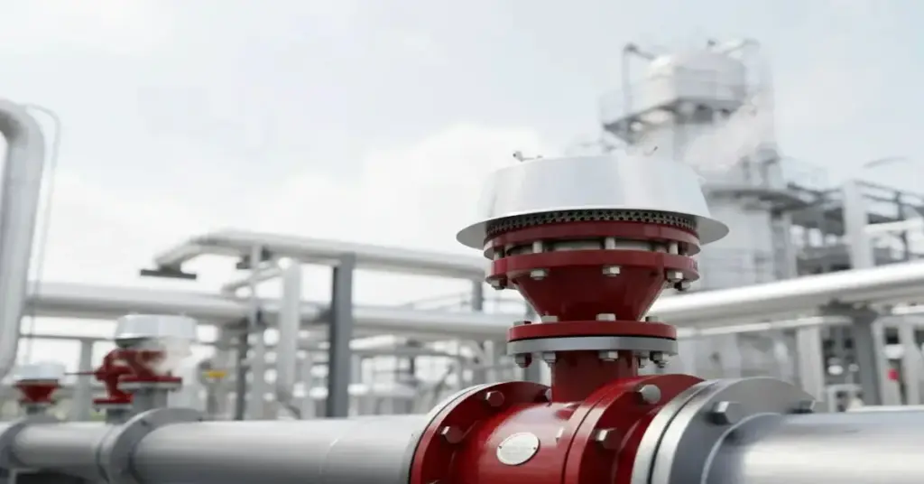
What is a Flame Arrester? A Full Guide (How They Work, Characteristics, & Uses) In industries that handle volatile liquids and gases, a spark is your worst enemy. If a fire starts outside a fuel tank, the real danger isn’t just the fire itself—it is the flame traveling back down the pipe into the tank, causing a catastrophic explosion. To stop this “flashback,” engineers rely on a critical passive safety device: the Flame Arrester. It acts as a firewall for your piping system, allowing gas to flow freely while stopping fire dead in its tracks. But selecting the wrong one (e.g., confusing a deflagration arrester with a detonation arrester) can be a fatal mistake. ADYAA supplies and distributes flame arresters in Australia, protecting local refineries, biogas plants, and storage terminals from disaster. In this guide, we break down the mechanics, functions, and critical applications of these life-saving devices. 1. What is a Flame Arrester? A flame arrester (also known as a flame trap) is a passive safety device installed on a storage tank nozzle or in a pipeline. Its primary function is simple but vital: to allow gas to pass through but stop a flame from passing through. It works on the principle of heat dissipation. By forcing the flame to pass through a series of narrow channels (the element), the device splits the flame into tiny “lets” and absorbs its heat energy until it becomes too cold to sustain combustion. 2. How Do They Work? (The Quenching Principle) The heart of every flame arrester is the “element” or filter bank—usually made of wound crimped metal ribbon or wire mesh. When a flame front hits the element, two things happen: Heat Transfer: The metal element acts as a massive heat sink. It absorbs the heat from the flame faster than the flame can generate it. Quenching: As the flame tries to squeeze through the tiny gaps (called the Maximum Experimental Safe Gap, or MESG), the temperature drops below the ignition point of the gas. The flame essentially “suffocates” and dies out. 3. Key Characteristics & Types Not all fires burn the same way. The type of flame arrester you need depends entirely on how fast the flame is moving and where the device is located. A. End-of-Line vs. In-Line End-of-Line: Installed at the very end of a pipe (e.g., a tank vent) to stop an atmospheric fire from entering the tank. In-Line: Installed in the middle of a pipe to stop a fire from traveling from one piece of equipment to another. B. Deflagration vs. Detonation This is the most critical distinction in safety engineering. Deflagration Arrester: Stops fires moving at subsonic speeds (slower than the speed of sound). Used for short pipe runs. Detonation Arrester: Stops fires moving at supersonic speeds (faster than sound). If a flame travels down a long pipe, it accelerates and creates a shockwave. Only a robust Detonation Arrester can stop this shockwave without shattering. 4. Applications & Use Cases Where are these devices mandatory? Fuel Storage Tanks: To protect diesel, petrol, or solvent tanks from external sparks or lightning strikes igniting the vapors inside. Biogas & Anaerobic Digesters: Methane lines in wastewater treatment plants are highly flammable. A flame arrester prevents a flare stack fire from traveling back into the digester. Vapor Recovery Units (VRU): When collecting fumes from truck loading racks, the piping network connects multiple tanks. Arresters isolate each tank to prevent a chain-reaction explosion. Marine Vessels: Ships carrying oil or chemicals use them to prevent engine room fires from reaching cargo holds. 5. Advantages of Using a Flame Arrester Why is this device essential for your safety strategy? Passive Protection: It has no moving parts, requires no power, and works instantly. Continuous Flow: It allows your system to “breathe” (venting pressure) while maintaining a safety barrier. Insurance Compliance: Most insurance policies for hazardous facilities require a certified flame arrester on all flammable storage vessels. Scalability: From small 1-inch vents to massive 24-inch pipeline units, they scale to fit any plant. 6. FAQ: People Also Ask Here are the answers to the most common questions regarding these safety systems. What is the purpose of a flame arrester? The purpose is to stop the propagation of a flame through a flammable gas or vapor mixture. It protects equipment (like storage tanks) and personnel by extinguishing the flame front before it can cause an explosion. Where are flame arrestors required? They are required anywhere flammable gases are vented or transported. Common locations include: Storage tank vents. Fuel gas lines feeding burners. Vapor recovery piping. Flare stack inlets. What is the purpose of a flame trap? “Flame trap” is simply another name for a flame arrester. Its purpose is to “trap” the flame by absorbing its heat, preventing it from passing further down the line. What is a flame arrester in a ship? On ships, they are installed on fuel tank vents and cargo hold vents. They prevent external sparks (from static electricity or machinery) from igniting the explosive fumes inside the fuel or cargo tanks. Conclusion: The Firewall for Your Pipes A flame arrester is a simple device with a massive responsibility. It stands between a minor fire and a major industrial disaster. Whether you are managing a biogas plant or a fuel terminal, selecting the right element size and location is non-negotiable. ADYAA supplies and distributes flame arresters in Australia, offering expert sizing and selection for Deflagration and Detonation hazards. We ensure your plant meets local safety standards. Is your facility protected from flashback? Explore ADYAA Flame Arresters View Tank Protection Systems Contact our Safety Engineers for a Site Review. How Industrial Automation Sensors Improve Automation & Efficiency in Manufacturing How Industrial Automation Sensors Improve Automation & Efficiency in Manufacturing In modern manufacturing, efficiency, accuracy, and reliability are more important… Read More → How Vision & Imaging Sensors Transform Automated Inspection Systems How Vision & Imaging Sensors Transform Automated Inspection Systems Maintaining product quality while keeping up with high-speed production is crucial….
Decoding the Datasheet: The Truth About Pressure Transmitter Accuracy
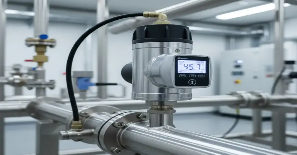
Decoding the Datasheet: The Truth About Pressure Transmitter Accuracy In the world of Industrial Pressure Sensors, “Accuracy” is the most expensive word on the datasheet. You see a shiny number like “±0.075%” printed in bold, and it’s natural to assume that’s exactly the error margin you’ll see on your control screen. But once you install that transmitter in the field—where it’s vibrating on a pump or baking in the Australian sun—the reality can be very different. This confusion leads to two common (and costly) mistakes: Over-specifying: Buying a Ferrari-level sensor for a go-kart application (wasting money). Under-specifying: Buying a cheap sensor that drifts constantly, ruining your process control. ADYAA, we believe the best customer is an educated one. So, let’s peel back the layers of the datasheet and explain what those accuracy specs actually mean for your plant. 1. The “Lab Number”: What Reference Accuracy Really Means The first number you see on a datasheet (e.g., ±0.075% of Span) is called Reference Accuracy. Think of this as the “Showroom Condition.” It tells you how the sensor performs in a perfect, air-conditioned laboratory with stable pressure and zero vibration. It is calculated using three specific test criteria, known as the “Big Three”: A. Linearity (The Straight Line) If you graph pressure vs. output signal, it should be a perfectly straight diagonal line. Linearity measures how much the sensor “wobbles” off that perfect path. If the linearity is bad, your DCS might say the tank is 50% full when it’s actually 51%. B. Hysteresis (The Memory Effect) Sensors have “muscle memory.” Going Up: You pressurize to 10 bar, and it reads 10.01 bar. Coming Down: You depressurize back to 10 bar, and it reads 9.99 bar. That difference is Hysteresis. It happens because the metal sensing diaphragm doesn’t snap back perfectly instantly. C. Repeatability (The Most Important Spec) If you hit the sensor with exactly 5 bar of pressure ten times in a row, does it give you the exact same number ten times? Repeatability is king. Even if a sensor is slightly off, if it’s repeatable, you can calibrate it to be perfect. If it’s not repeatable, it’s untrustworthy. The Reality Check: Reference Accuracy only tells you how good the sensor can be. It doesn’t tell you how good it will be in your plant. 2. The Real World: Why Accuracy Drops in the Field Your plant isn’t a laboratory. It’s hot, noisy, and dirty. These environmental factors introduce new errors that are not included in that headline “0.075%” number. Temperature Effect (The Sun Factor) Liquids expand when they get hot. Inside a Pressure Transmitter, there is a tiny amount of oil that transfers pressure to the sensor. The Problem: If your transmitter sits in the 40°C afternoon sun and then cools down to 10°C at night, that internal oil expands and contracts. This causes the “Zero” point to drift. The Fix: High-quality sensors use “Active Temperature Compensation” to mathematically correct this error in real-time. Cheap sensors do not. Static Pressure Effect This is a big one for Differential Pressure (DP) flow measurement. If you are measuring a tiny pressure drop across an orifice plate, but the pipe itself is pressurized to 50 bar, that massive static pressure squeezes the sensor body. This physical stress shifts the reading. 3. The https://www.google.com/search?q=%231 Mistake: ignoring “Turndown Ratio” This is the most common reason we see “accurate” sensors giving bad data. Turndown Ratio is how much of the sensor’s range you are actually using. Accuracy is usually a percentage of the Maximum Range, not your calibrated set point. Scenario: You buy a sensor rated for 0-100 bar. The Mistake: You only use it to measure 0-5 bar. The Result: That tiny error margin at 100 bar becomes a huge error margin when you are only looking at 5 bar. Engineer’s Tip: Always buy a sensor range that is closest to your actual operating pressure. Don’t buy a 100 bar sensor to measure 5 bar “just in case.” 4. The “Real” Number: Total Probable Error (TPE) If you want to know the honest accuracy of a device, you need to calculate the Total Probable Error (TPE). This isn’t usually printed on the datasheet, but it’s the number that matters. It combines the Lab Accuracy with the Temperature and Static Pressure effects. Standard Sensor: Might claim 0.075% accuracy, but the real TPE is 0.25%. High-End Sensor: Might claim 0.04% accuracy, and the real TPE is 0.10%. Why does this matter? If you are calculating the efficiency of a million-dollar boiler, that difference is massive. 5. Which Sensor Tier Do You Actually Need? At ADYAA, we help you save money by matching the right tier to the right job. You don’t need a Porsche to drive to the grocery store. Tier 1: Standard Industrial (±0.25% – ±0.5%) Use for: Monitoring pumps, water tank levels, compressed air lines. Why: You just need to know if the pressure is stable. Close enough is good enough. Tier 2: Precision Process (±0.075%) Use for: Chemical reactors, steam flow, critical control loops. Why: A small error here could ruin a batch or waste energy. Tier 3: High Performance (±0.04% or better) Use for: Custody transfer (selling oil/gas), leak testing, calibration labs. Why: When every drop of product equals money, you pay for the best. Final Thoughts Don’t let the specs intimidate you. Understanding Pressure Transmitter Accuracy is simply about matching the tool to the environment. ADYAA, supplies, we don’t just ship boxes. Our engineering team can help you calculate the Total Probable Error for your specific application, ensuring you get a sensor that is accurate enough to keep you safe, without blowing your maintenance budget. Need help selecting the right pressure transmitter? Explore the ADYAA Pressure Range Contact us for a TPE Calculation. How Industrial Automation Sensors Improve Automation & Efficiency in Manufacturing How Industrial Automation Sensors Improve Automation & Efficiency in Manufacturing In modern manufacturing, efficiency, accuracy, and reliability are more important… Read More → How Vision & Imaging Sensors